VIVOTEK
4 - User's Manual
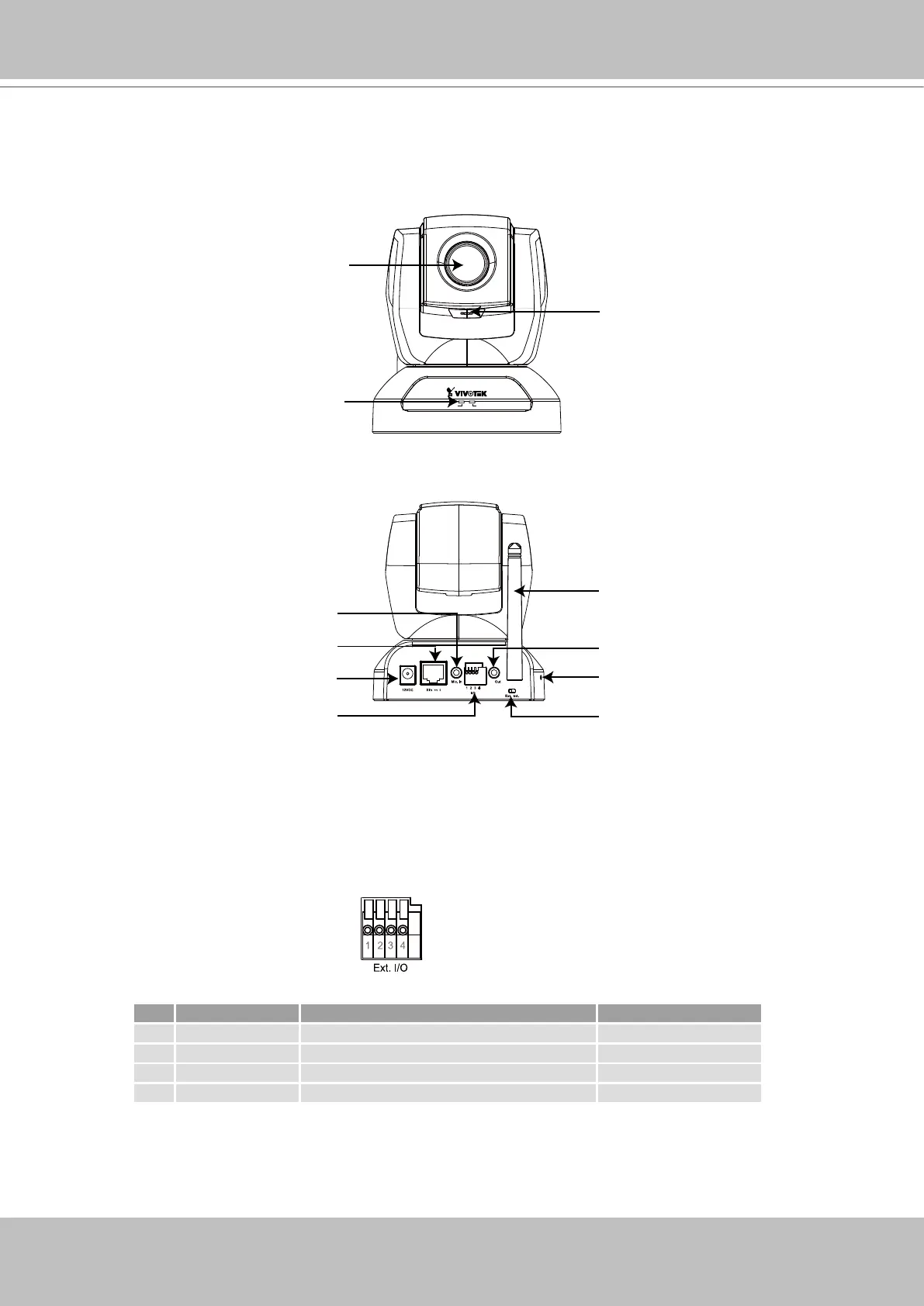
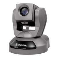
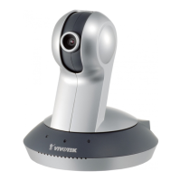
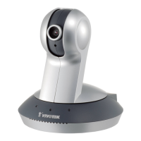
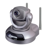
Physical Description
Front panel
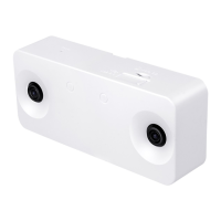
Rear panel
General I/O Terminal Block
This Network Camera provides a general I/O terminal block which is used to connect external
input / output devices. The pin denitions are described below.
1: Power
2: Digital output
3: Digital input
4: Ground
Built-in Microphone
Status LED
Lens
Recessed Reset Button
Ethernet 10/100
RJ45 Socket
External/Internal
Microphone Switch
General I/O
Terminal Block
AV Out
Microphone In
Power Cord Socket
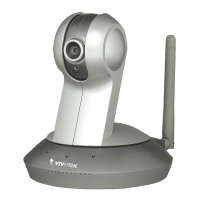
Antenna
(PZ7112 / PZ7122 only)
Pin Name Specification Remarks
1 Power 12VDC ± 5%, max� 1�5A Max� rating 2A
2 Digital output Max� 40VDC, max� 400mA, isolation 2kV
3 Digital input OPEN/Short-to-GND, isolation 2kV Internal pull-up
4 Ground