VIVOTEK
User's Manual - 5
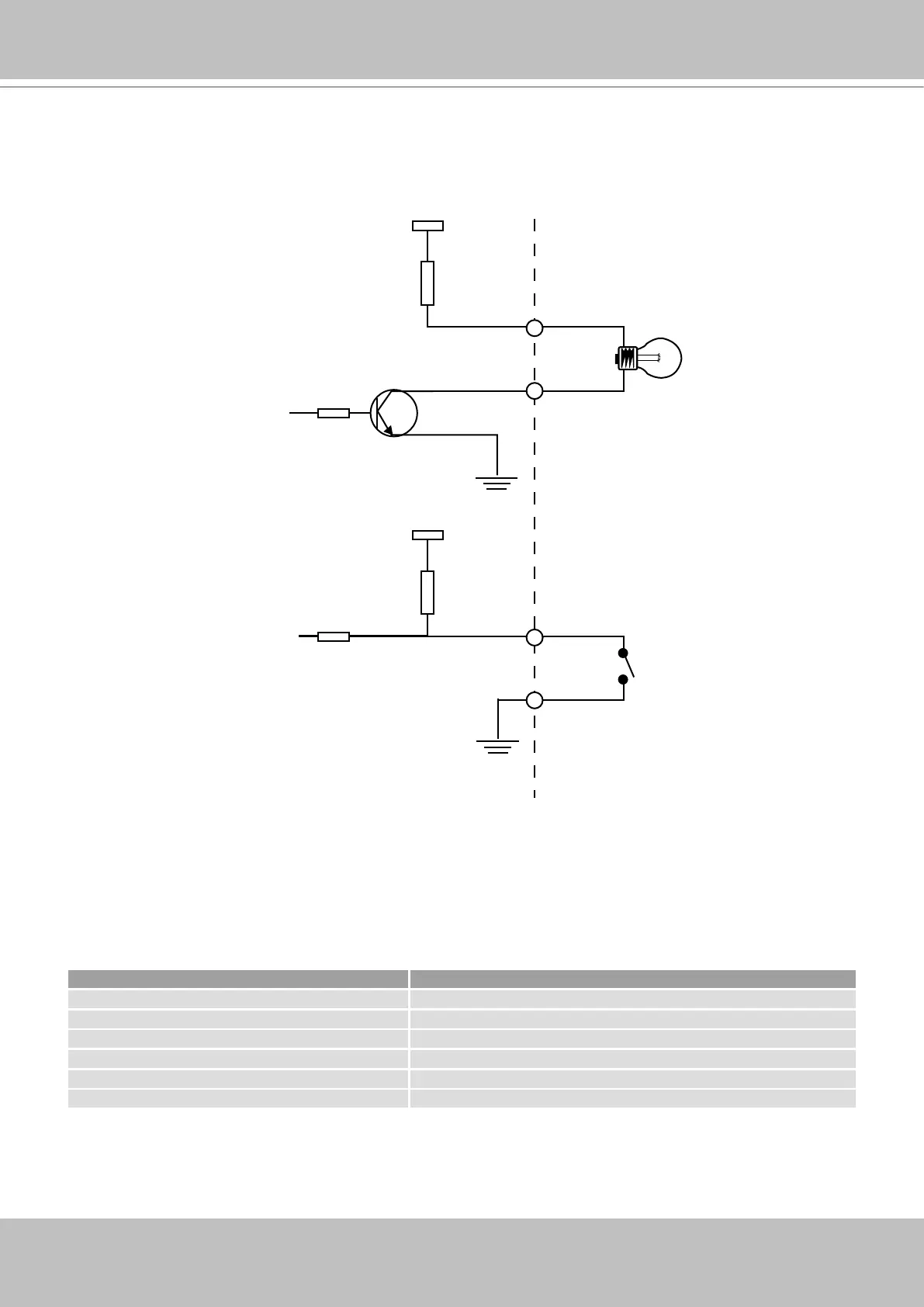
DI/DO Diagram
Please refer to the following illustration for the connection method�
Status LED
The color of LED indicates the status of the Network Camera�
Status LED Color Description
Blinking red Power is being supplied to the Network Camera�
Solid green The Network Camera is booting up�
Steady green with blinking red The Network Camera is trying to obtain an IP address�
Steady green and red An IP address is successfully assigned to the Network Camera�
Steady red with blinking green The Network Camera is working�
Blinking red and green During firmware upgrade�
12V
+12V
Digital output
PIN 1
Power+12V
PIN 2
Digital input
PIN 3
Ground
PIN 4