Vixel 9000 Series Installation & Configuration Guide CHAPTER 2 Installing and Connecting
6
Installing
You can place the switch on a desktop or install the switch into an equipment rack.
(To rack-mount the switch, see the documentation that shipped with the rack-
mounting kit, which is sold separately.)
To place the switch on a desktop:
1. Turn the switch upside down so the case bottom is facing up.
2. Install a self-adhesive pad on each corner of the switch (prevents surface
damage).
3. Turn the switch right side up so the case bottom is facing down.
Note: The plug on the
power cord is intended to
serve as the disconnect
device. To cycle power to
the switch, remove and
reconnect the switch’s
power cord.
4. Attach one end of the switch’s power cord to the switch’s power inlet socket and
the other end to a properly earthed receptacle (outlet).
The switch is now powered on. The switch automatically executes a Power-On
Self Test (POST) and its LEDs display the test results (for a description of the
POST sequence, see “Powering On the Switch and Interpreting the LEDs” on
page 6).
Powering On the Switch and Interpreting the LEDs
When you plug in the Vixel 9000 Series Switch, the power and fault LEDs are the
only LEDs in a known state—all other LEDs are unknown and must be initialized.
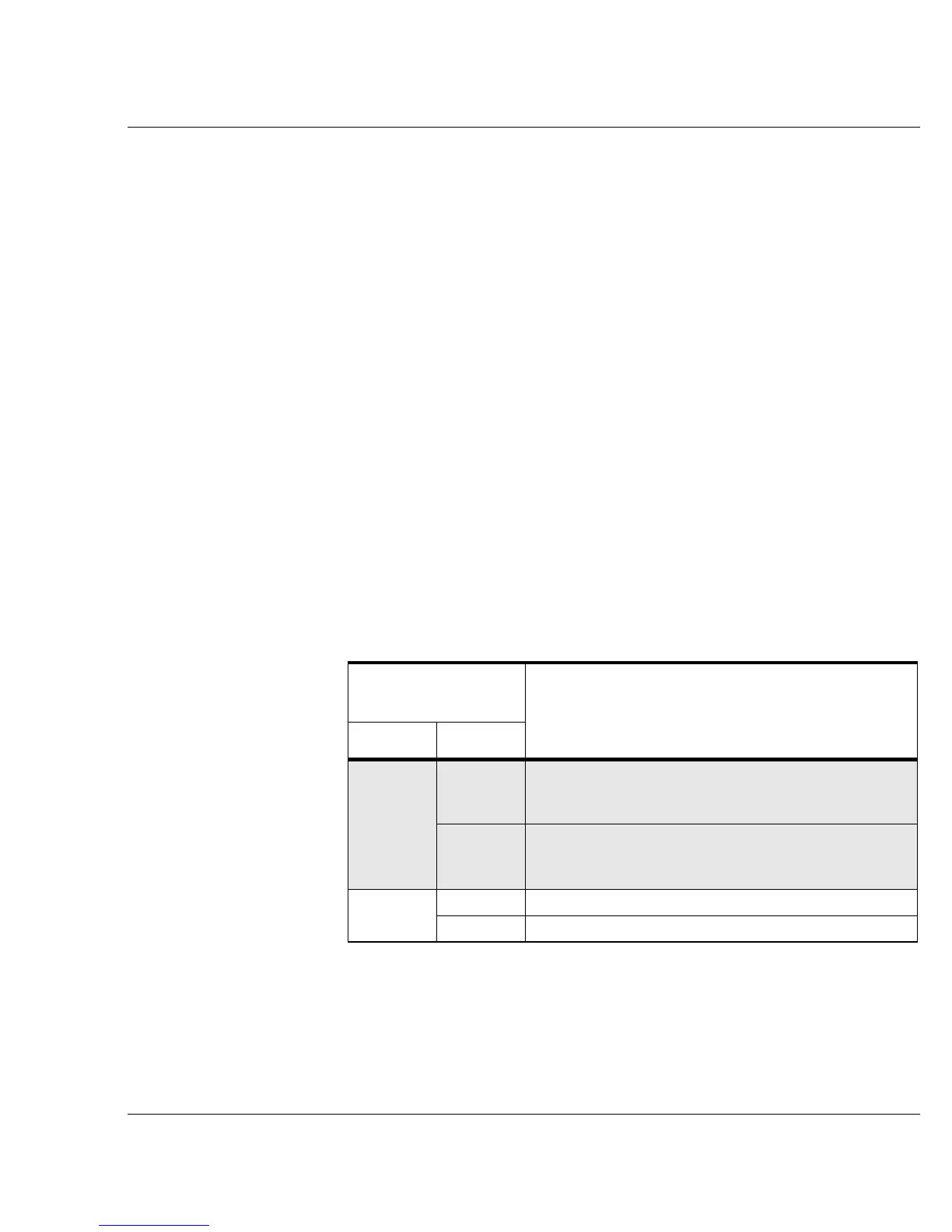
The power-fault combinations and their indications are listed below.
System LED and
State
Indication during Power-On Self Test (POST)
Power Fault
Off
Off Field Programmable Gate Arrays (FPGAs) failed to load
or the power to the switch is inadequate. (For power
requirements, see “Operating Conditions” on page 51.)
Solid The Central Processing Unit (CPU) did not get started; a
bus integrity problem may exist. Contact an authorized
service person.
Solid
Off Normal operation.
Solid CPU starts but system abilities are limited.
 Loading...