Vixel 9000 Series Installation & Configuration Guide APPENDIX A Physical Description
48
Ports and LEDs
The Vixel 9000 Series Switch is equipped with eight or sixteen Fibre Channel ports.
LEDs are shown in Figure 6-1.
Note: The blinking rates
vary according to the LED.
While port LEDs blink at
one rate only, the Fault
LED can blink at either
slow or fast rate, and the
ACT/COL LED blinks
randomly, according to the
activity on the Ethernet
port. The Power and 100
LEDs do not blink.
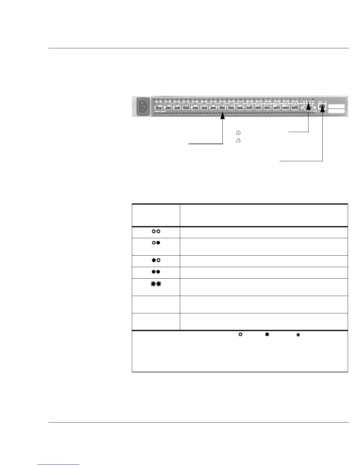
Port, System, and Ethernet LED indications are shown in the tables below.
Figure 6-1. LEDs on the Vixel 9200 Switch (business end)
Port status LEDs
(health and activity):
green at left,
yellow at right
System LEDs:
Power (green),
Fault (yellow)
Ethernet LEDs:
ACT/COL (left)
100 (right)
Port LED
Appearance*
Health Indication on a Vixel 9000 Series Switch
(During Run-Time)
No transceiver inserted.
Port is bypassed; the transceiver may have a transmitter (Tx)
fault.
Transceiver is inserted and good; communication is established.
Transceiver is inserted and good, but no link is established.
Port has been set to “beaconed” through SAN InSite or another
management tool.
blinking yellow
port LED
Port is being manually controlled (for example, taken off-line
or beaconed) through SAN InSite or another management tool.
flickering green
port LED
Port is active (traffic is going through the port).
* Legend for the port LED appearance: = unlit; = lit; and = blinking. The
left LED represents the green LED; the right LED represents the yellow LED.
Note: A steadily blinking green LED (lit for 1/2 second, unlit for 1/2 second) and
solid yellow LED combination indicate that the port is attempting to bring the link
up and establish protocol connect with a device.
 Loading...