19
5.1 GAS SUPPLY INSTALLATION
Inspect the entire installation including the gas meter, test for
tightness and purge. Refer to BS 6891 (I.S. 813 in ROI) for
specifi c instruction.
5.2 THE HEATING SYSTEM
The appliance contains components that may become damaged
or rendered inoperable by oils and/or debris that are residual
from the installation of the system, consequently it is essential
that the system be fl ushed in accordance with the following
instructions.
5.3 INITIAL FILLING OF THE SYSTEM
Ensure both fl ow and return service valves are open, remove
appliance casing as described in 4.7.1, identify the automatic air
release valves (AAV) and loosen the dust cap/s by turning the
cap anti-clockwise one full turn. Ensure all manual air release
valves located on the heating system are closed. Connect the
fi lling loop, slowly proceed to fi ll the system by fi rstly opening
the inlet valve connected to the fl ow pipe, and then turning the
lever on the fi ll valve, to the open position. As water enters the
system the pressure gauge will begin to rise. Once the gauge
has reached 1 BAR close both valves and begin venting all
manual air release valves, starting at the lowest fi rst. It may be
necessary to go back and top-up the pressure until the entire
system has been fi lled. Inspect the system for water tightness,
rectifying any leaks.
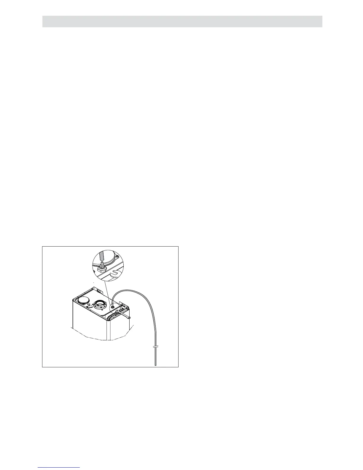
5.3.1 MANUAL AIR RELEASE (fi g. 27)
When the boiler has been fi lled for the fi rst time or the system
has been drained and refi lled, it will be necessary to release
any air that may have become trapped within the appliance heat
exchanger. Slacken the bleed screw until water is released
and then close.
IMPORTANT, THERE ARE NO OTHER MANUAL AIR RE-
LEASE VALVES LOCATED ON THE APPLIANCE.
5.4 INITIAL FLUSHING OF THE SYSTEM
The whole of the heating system must be fl ushed both cold
and hot as detailed in 5.8. Open all radiator or heating valves
and the appliance fl ow & return service valve. Drain the boiler
and system from the lowest points. Open the drain valve full
bore to remove any installation debris from the boiler prior to
lighting. Refi ll the boiler and heating system as described in 5.3.
5.5 PRE-OPERATION CHECKS
Before attempting the initial lighting of the appliance, the fol-
lowing checks must be carried out:
• ensure all gas service valves from the meter to the appliance
are open and the supply pipe has been properly purged;
• ensure the proper electrical checks have been carried out,
Fig. 27
(see 7.8) particularly continuity, polarity and resistance to
earth;
• ensure the 3 AMP fuse – supplied with the appliance – has
been fi tted;
• ensure the system has been fi lled, vented and the pressure
set to 1 BAR;
• ensure the fl ue system has been fi tted properly and in ac-
cordance with the instructions;
• ensure all appliance service valves are open.
5.6 INITIAL LIGHTING
Ensure the electrical supply to the appliance is switched on.
Ensure any external controls are switched to an ‘ON’ position
and are calling for heat. Move the selector switch to the ON
position, the appliance will now operate as described in 1.2.
Should the appliance fail to ignite, refer to 5.6 and/or section 7
(mode of operation, parameter setting & faultfi nding).
5.7 CHECKING GAS PRESSURE AND COMBUS-
TION ANALYSIS
The appliance is factory set so should require no additional
adjustment once installed. However to satisfy the requirements
of GSIUR 26/9 (I.S. 813 ROI), it will be necessary to gas rate
the appliance using the gas meter that serves the appliance
and carry out a combustion analysis check in accordance with
BS 7967 (UK) to ensure that correct combustion is occurring,
see fl ow chart on page 37.
Additionally, if the gas valve has been adjusted, replaced, or the
appliance has been converted for use with another gas type,
then it becomes necessary to carry out a combustion analysis
check to ensure that correct combustion is occurring.
If there are no means to carry out a combustion analysis check,
then it will not be possible to complete the commissioning
procedure.
Details on how to carry out the combustion analysis can be
found in section 7.
IMPORTANT
It’s imperative that a suffi cient dynamic – gas – pressure is
maintained at all times. Should the dynamic gas pressure fall
below an acceptable level, the appliance may malfunction or
sustain damage.
5.8 FINAL FLUSHING OF THE HEATING SYSTEM
The system shall be fl ushed in accordance with BS 7593 (I.S.
813 ROI). Should a cleanser be used, it must be suitable for
Aluminium heat exchangers. It shall be from a reputable manu-
facturer and shall be administered in strict accordance with the
manufacturers’ instructions and the DWTA code of practice.
NOTE
Chemicals used to cleanse the system and/or inhibit corrosion
must be pH neutral, i.e. they should ensure that the level of the
pH in the system water remains neutral. Premature failure of
certain components can occur if the level of pH in the system
water is out-with normal levels.
5.8.1 INHIBITORS
See Section 3 “General Requirements”.
5.9 SETTING THE FLOW OUTLET TEMPERA-
TURE
The fl ow outlet temperature can be adjusted between 40 °C -
80 °C for standard CH system by using the Heating thermostat
knob (see fi g.1).
5.9.1 SETTING THE DHW OUTLET TEMPERATURE
The DHW outlet temperature can be adjusted between 37 °C
- 60 °C via the DHW thermostat knob (see fi g.1).
5.10 SETTING THE SYSTEM DESIGN PRESSURE
The design pressure should be a minimum of 0.5 BAR and a
maximum of 1.5 BAR. The actual reading should ideally be 1
BAR plus the equivalent height in metres (0.1 BAR = 1 metre) to
the highest point in the system above the base of the appliance
(up to the maximum of 1.5 BAR total). N.B. The safety valve
SECTION 5 - COMMISSIONING