24
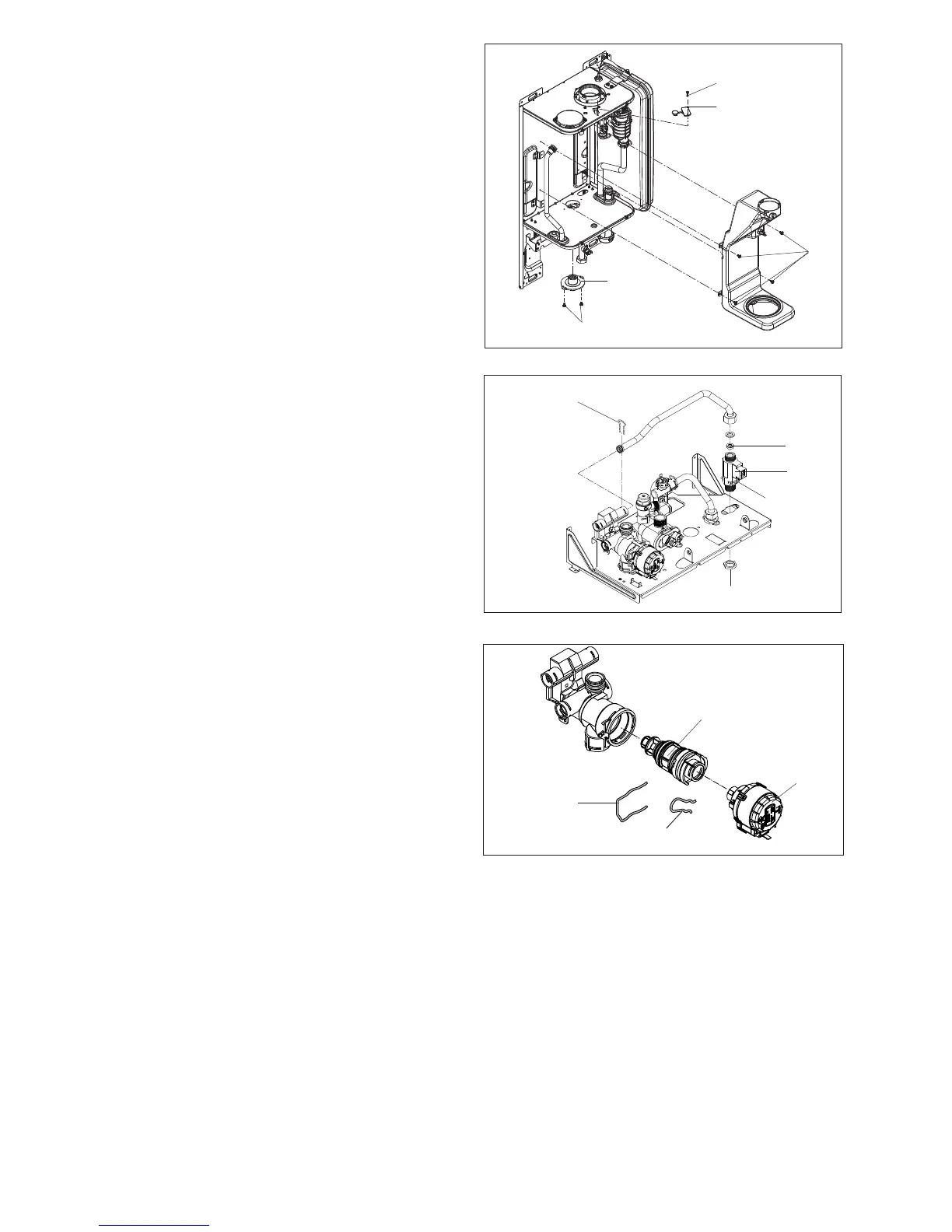
6.20.3 VALVE ACTUATOR (fi g. 43)
Carry out component removal procedure as described in 6.4.
Remove the locking pin (G3) that secures the actuator (H2) to
the heating manifold. Disconnect the electrical plug from the
actuator. Replace in the reverse order.
6.20.4 DHW THERMISTOR (fi g. 32)
Carry out component removal procedure as described in 6.4.
Locate and remove the thermistor locking pin (I2). Gently ease
the thermistor assembly (J2) from the hydraulic manifold. Re-
place in the reverse order.
6.20.5 DIVERTOR VALVE ASSEMBLY (fi g. 43)
Carry out component removal procedure as described in 6.4.
Remove the valve actuator as described in 6.20.3. Locate and
remove the locking pin (G2) that secures the valve housing
cover to the hydraulic manifold. Gently prise the valve as-
sembly from the manifold (K2). Replace in the reverse order
ensuring that the seating assembly is inserted properly. Ensure
all seals are in good condition, taking care to ensure they are
replaced correctly.
G2
Fig. 43
6.20.2 DHW FLOW SWITCH (fi g. 42)
Carry out component removal procedure as described in 6.4.
Remove the locking pin (D2). Disconnect and remove the cold
water inlet pipe from the DHW fl ow switch & DHW heat ex-
changer. Disconnect the wiring to the DHW fl ow switch. Slacken
and unscrew the inlet connection. Unscrew the nut (E2). Lift the
DHW fl ow switch housing from its seating. If necessary remove
the locking pin (F2) from the DHW fl ow switch, taking care not
to lose the fl oat contained within the housing.
Replace in the reverse order ensuring that the housing is fi rmly
inserted onto its seating. Ensure all seals are in good condition,
taking care to ensure they are replaced correctly.
Fig. 42
H2
K2
B2
C2
D2
E2
F2
Fig. 41
6.20 FLUE COLLECTOR REMOVAL (fi g. 41)
Carry out component removal procedure as described in 6.4.
Remove the air chamber front cover. Remove the heat exchang-
er as per 6.16. Locate and remove the screw (Y1) that secures
the fl ue gas analysis test point cover (Z1). Disconnect the fl ues
thermistor wiring connections. Locate and remove the 4 screws
(A2). Locate and remove the 2 screws (A3). Gently ease the
condensate collector (A4) out off its location. Gently ease the
fl ue collector out off its location. Replace in the reverse order.
6.20.1 DHW FLOW RESTRICTOR (fi g. 42)
Carry out the component removal procedure as described in
6.4.
Disconnect the cold water inlet pipe at the DHW fl ow switch
(B2). Using a small screwdriver, gently ease the fl ow restrictor
(C2) from its seating. Replace in the reverse order. Ensure
all seals are in good condition, taking care to ensure they are
replaced correctly.
G3
Y1
Z1
A2
A3
A4