31
8.1 EXTERNAL WIRING
The appliance comes with a factory fi tted (TA) link to allow
basic operation of the boiler via the mode selector switch. If
external controls are to be added to the system, they must be
connected to the appliance as shown in the following diagrams.
For advice on controls that are not featured in this book, please
contact Vokèra technical on 0844 391 0999.
8.1.1 EXTERNAL WIRING LIMITATIONS
Any external wiring must remain within the limits as detailed:
room thermostat = 30-metres
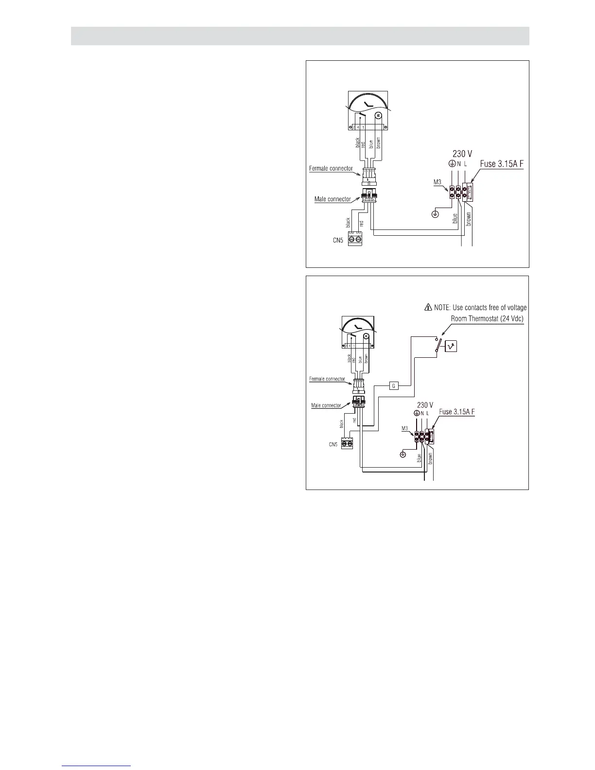
8.2 TYPICAL CONTROL APPLICATIONS
The appliance can be used with the following controls:
• single-channel, voltage-free time clocks (fi g. 49)
• single-channel, voltage-free time clocks + room thermostats
(fi g. 50)
• programmable RF room thermostats (fi g. 49)
• low voltage (24Vdc) room thermostat (CN5 fi g. 49)
8.3 OTHER DEVICES
Contact the controls manufacturer and/or Vokèra technical
department should you require more specifi c information on the
suitability of a particular control. Further guidance on the recom-
mended practice for the installation of external controls, can be
found in CHeSS – HC5/HC6 (www.energyeffi ciency.gov.uk).
8.4 VOKÈRA LOWER COVER MECHANICAL
CLOCK (fi g. 4)
The Vokèra lower cover mechanical clock kit (product code
20025081) is entirely suitable for the Compact A range and
eliminates the need for an external time control.
The kit is comprised of the following:
• lower cover
• mechanical clock
• wiring harness
• instructions
Isolate the appliance from the electrical supply, remove the
boiler casing (see 4.7.1) and locate the factory fi tted connector
plug and connect to the corresponding plug supplied with the
mechanical clock wiring harness.
To add a room thermostat, identify the 2 switch wires (black/red
colour in terminal block (CN5) and connect the room thermostat
wires in series in terminal block CN5 (see fi g. 50)
Refi t the boiler casing.
Fit the cover kit to the boiler.
IMPORTANT
• The boiler must always be supplied with a permanent 230V
electrical supply.
• Always remove the link between TA & TA on the CN5 PCB
terminal (see fi g. 49)
• The room thermostat connection is low voltage (24 Vdc)
• Do not connect any controls or auxiliary equipment to the
low-voltage terminal strip, other than that approved/supplied
by Vokèra Ltd.
Fig. 49
Fig. 50
SECTION 8 - WIRING DIAGRAMS
MECHANICAL CLOCK -
RADIO FREQUENCY RECEIVER