32
FUNCTIONAL DIAGRAM
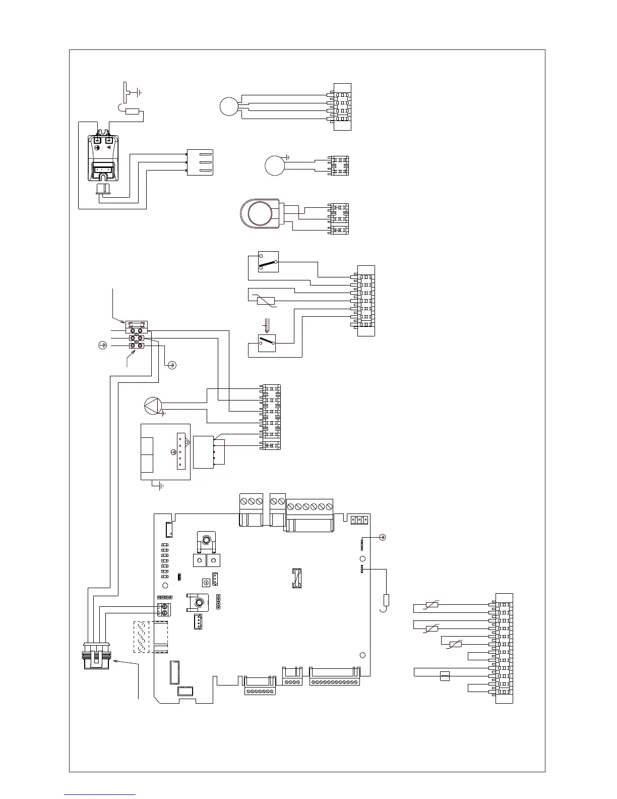
Fig. 51
NOTE: L-N-E connection is advisable
brown
CN3
blue
F Hv
1
2
7
1
CN9
W.P.S.
2
3
1
D.H.W.T.
D.H.W.F.S.
white
white
red
red
violet
violet
3W
2
N
1
D.H.W.
3
Heat
black
brown
blue
3
1
CN4
6
1
CN2
brown
blue
2
1
3
5
4
GAS VALVE
12 43
OPEOPE
pink
blue
P
brown
N
L
Fuse 3.15A F
230 V
M3
F
blue
blue
brown
brown
brown
blue
brown
blue
1
2
3
AMP
1
2
3
AMP
black
red
blue
brown
44
Connector
clock
CN8
CN7
1
12
CN11
1
4
CN10
1
7
CN9
CN6
CN5
CN12
1
CN4
1
3
CN3
1
2
CN2
1
6
AKL
CN1
1
FA1
FA2
arancione
E.R.
JP1
JP2
JP3
JP4
JP5
JP6
JP7
JP8
CN15
P3
P2
P1
CN13
CN14
SW1
P4
F1
3.15A T
TSC2
blue
Spark
electrode
brown
yellow/green
N
F
CN1
3
1
2
red (+)
blue (HS)
pink (PWM)
grey (-)
CN10
F Lv
1
4
1
12
CN11
white
white
F.T.
-t°
-t°
R.S.
red
red
-t°
F.S.
grey
grey
black
F.O.HT.
blue
blue
white
AKL Main PCB with vis medium integrated
P1 Selector switch and heating potentiometer
P2 DHW potentiometer
P3 Unused
P4 Unused
JP1 Unused
JP2 Unused
JP3 Unused
JP4 Unused
JP5 Unused
JP6 Unused
JP7 Unused
JP8 Closed - Unused
CN1-CN15 Connectors - CN5 Room thermostat (24 Vdc)
S.W. CO2 function button
F.S. (1) Flame sensor
F1 Fuse 3.15A T
F External fuse 3.15A F
M3 Terminal strip for electrical connection hight power
P Pump
OPE Gas valve solenoids
F Hv Fan power supply 230 V
F Lv Fan signal control
D.H.W.F.S Domestic hot water fl ow switch
D.H.W.T Domestic hot water temperature
WPS Water pressure switch
S.E Spark electrode
TSC2 Ignition transformer
3W 3 way motor
F.O.H.T Flow over heat thermostat
FS Flue sensor
FT Flow thermistor (NTC)
RS Return thermistor (NTC)