4
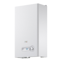
3.1 HOW TO TOP-UP THE SYSTEM PRESSURE
(fi g. 1-2)
The system pressure must be checked periodically to ensure the
correct operation of the boiler. The needle on the gauge should
be reading between 1 and 1.5 BAR when the boiler is in an off
position and has cooled to room temperature. If the pressure
requires ‘topping-up’ use the following instructions as a guide.
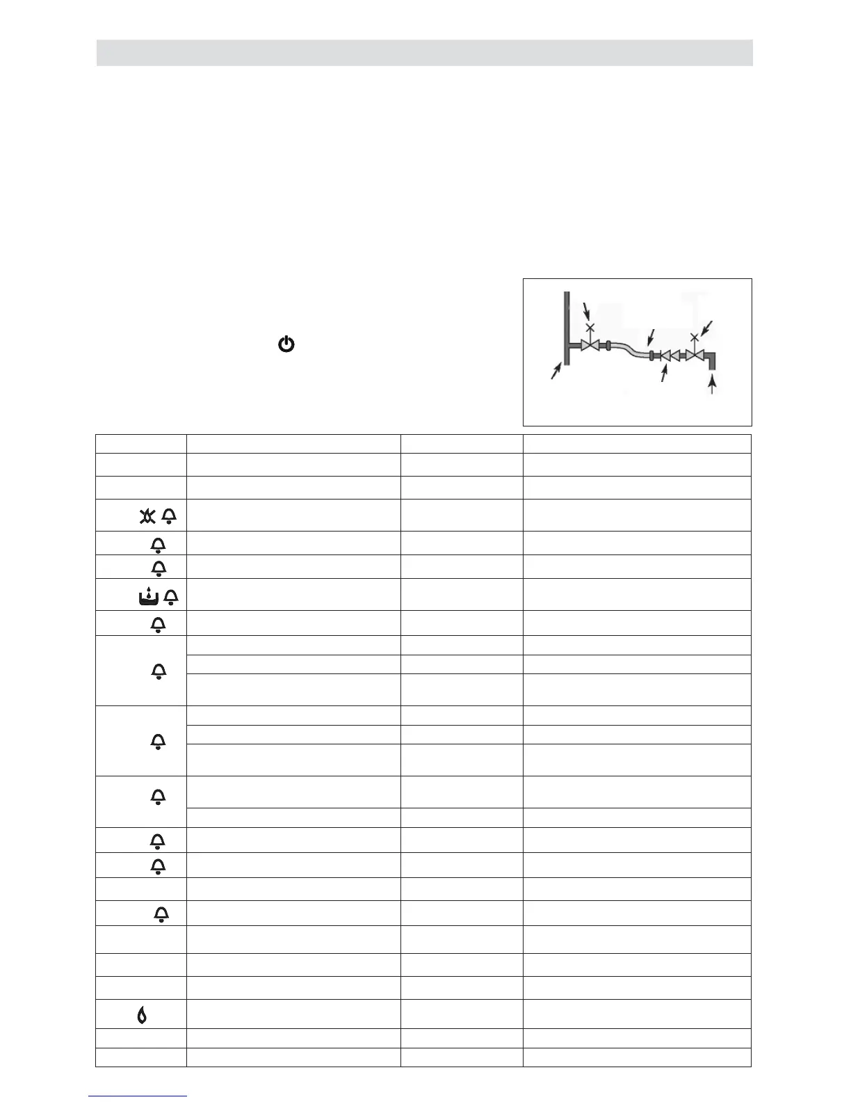
- Locate the fi lling valve connections (usually beneath the
boiler, see fi g. 3).
- Attach the fi lling loop to both connections.
- Open the fi lling valve slowly until you hear water entering the
system.
- Close the fi lling valve when the pressure gauge (on the boiler)
reads between 1 and 1.5 BAR (see fi g. 1).
- Remove the fi lling loop from the connections.
3.2 HOW TO RESET THE APPLIANCE
When the fault code is displayed, the appliance will require to
be reset manually. Before resetting the boiler, check what action
is required to be taken, using the information on the fault code
table below. Allow a period of two minutes to elapse before rotate
the mode selector knob across the position (see fi g. 1).
IMPORTANT
If the appliance requires to be reset frequently, it may be indica-
tive of a fault, please contact your installer or Vokèra Customer
Services for further advice.
3. HOW TO...
Fig. 3
control
valve
temporary
connection
control
valve
supply pipe
double
check valve
fl ow/return
pipe
3.3 HOW TO SHUT DOWN THE SYSTEM FOR
SHORT PERIODS
The system and boiler can be shut down for short periods by
simply turning the time clock to the off position. It is also advis-
able to turn off the main water supply to the house.
3.4 HOW TO SHUT DOWN THE SYSTEM FOR
LONG PERIODS
If the house is to be left unoccupied for any length of time –
especially during the winter – the system should be thoroughly
drained of all water. The gas, water, and electricity supply to
the house should also be turned off. For more detailed advice
contact your installer.
3.5 HOW TO CARE FOR THE APPLIANCE
FAULT CODES
ALARM CODE CAUSE ALARM TYPE ACTION
_St
AUTOSTOP Final Call engineer
_CL
CALL FOR SERVICE Temporary then fi nal Call engineer
A01
Ignition failure, fl ame not sensed,
internal fault
Final Reset, check appliance operation
A02
Limit thermostat fault Final Reset, check appliance operation
A03
Fan tacho signal fault Final Reset check appliance operation, check fan
A04
Insuffi cient system water pressure Final
Check/refi ll system pressure, reset, check
appliance operation
A06
DHW thermistor fault Temporary Check DHW thermistor
A07
Primary (fl ow) thermistor fault Temporary Check primary thermistor, check wiring
Primary (fl ow) thermistor over temperature
Temporary then fi nal Reset, check appliance operation
Temperature differential Final
Reset, check appliance operation, check
thermistors
A08
Return thermistor fault Temporary Check return thermistor, check wiring
Return thermistor over temperature Temporary then fi nal Reset, check appliance operation
Temperature differential inverted Final
Reset, check pump, ensure there is suf-
fi cient circulation around heating circuit/s
A09
Flue thermistor or fl ue thermistor
counter fault
Temporary
Check fl ue thermistor counter at power
on, check fl ue thermistor, check wiring
Flue thermistor over temperature Final Reset, check appliance operation
A11
False fl ame Temporary None
A77
Low temperature thermostat fault Temporary Check low temperature thermostat
Adj
Calibration Na None
ACO
Service operation Na None
Purge cycle mode active Na None
P
Preheating function active Na None
P blinking
Preheating function running Na None
Flame ON Na None
Hours Stand-by Na None
- - OFF Na None
To clean the
outer cas-
ing use only
a clean damp
cloth. Do not
use any scour-
ers or abrasive
cleaners.