17
4.6 CONNECTING THE GAS AND WATER
The appliance is supplied with an accessory pack that includes
service valves.
The service valves are of the compression type.
The accessory pack contains sealing washers’ etc, for use
with the service valves. When connecting pipe work to the val-
ves, tighten the compression end fi rst then insert the sealing
washers before tightening the valve to the appliance.
NOTE
It will be necessary to hold the valve with one spanner whilst
tightening with another.
4.6.1 GAS (fi g. 24)
The appliance is supplied with a 15mm service valve, connect
a 15mm pipe to the inlet of the valve and tighten both nuts.
NOTE
It will be necessary to calculate the diameter of the gas supply
pipe to ensure the appliance has an adequate supply of gas.
4.6.2 FLOW & RETURN (fi g. 24)
The appliance is supplied with 22mm service valves for the
fl ow and return connections, connect a 22mm pipe to the inlet
of each valve and tighten both nuts.
NOTE
Depending on system requirements, it may necessary to in-
crease the size of the fl ow & return pipe work after the service
valve connections.
4.6.3 COLD WATER INLET (fi g. 24)
The appliance is supplied with a 15mm stopcock, connect a
15mm pipe to the inlet of the stopcock and tighten both nuts.
4.6.4 HOT WATER OUTLET (fi g. 24)
The appliance is supplied with a 15mm outlet connection, con-
nect a 15mm pipe to the outlet connection and tighten both nuts.
4.6.5 SAFETY VALVE (fi g. 24)
Connect the safety valve connection pipe to the safety valve
outlet and tighten. The discharge pipe must have a continuous fall
away from the appliance to outside and allow any water to drain
away thereby eliminating the possibility of freezing.
The discharge pipe must terminate in a position where any water
- possibly boiling - discharges safely without causing damage or
injury, but is still visible.
4.6.6 CONDENSE PIPE
During normal operation the boiler produces condense which
is collected in a trap located in the lower part of the boiler. A
fl exible pipe (condense outlet pipe) is connected to the outlet
of the trap. The fl exible pipe must be connected to a plastic
waste pipe only. The plastic waste pipe must have a minimum
of a 3º fall towards the drain. Any external run of pipe should
be insulated to prevent the risk of freezing.
4.6.7 CONNECTING THE CONDENSATE OUTLET
Gently pull the condense outlet pipe down from its location
inside the boiler until approximately 100mm protrudes from the
underside of the boiler, care should be taken to ensure that the
pipe connection to the trap remains secure. Connect a suitable
plastic (not copper) pipe (no less than 21mm diameter) to the
outlet pipe and ensure it discharges in accordance with local
building regulations or other rules in force.
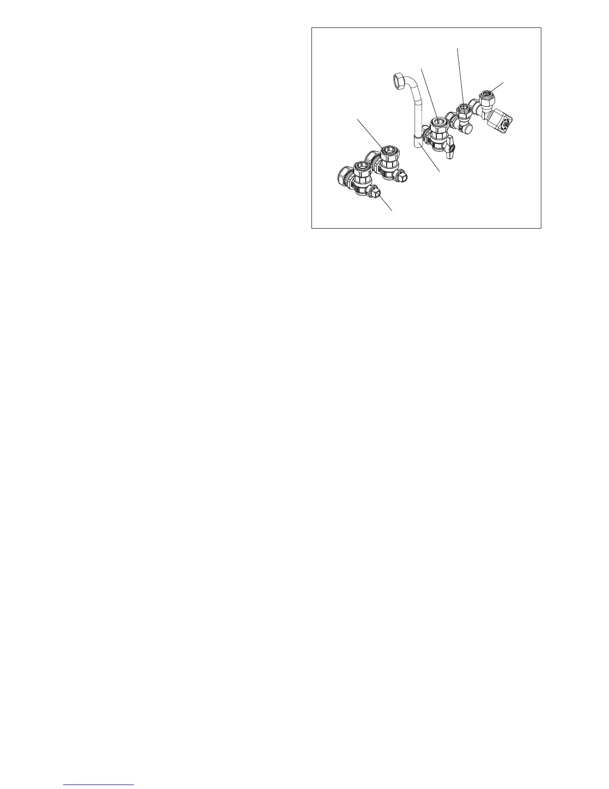
Fig. 24
Hot water outlet
Cold water inlet
stopcock
Gas cock
C/H fl ow valve
C/H return valve
Safety valve outlet