16
Fig. 19
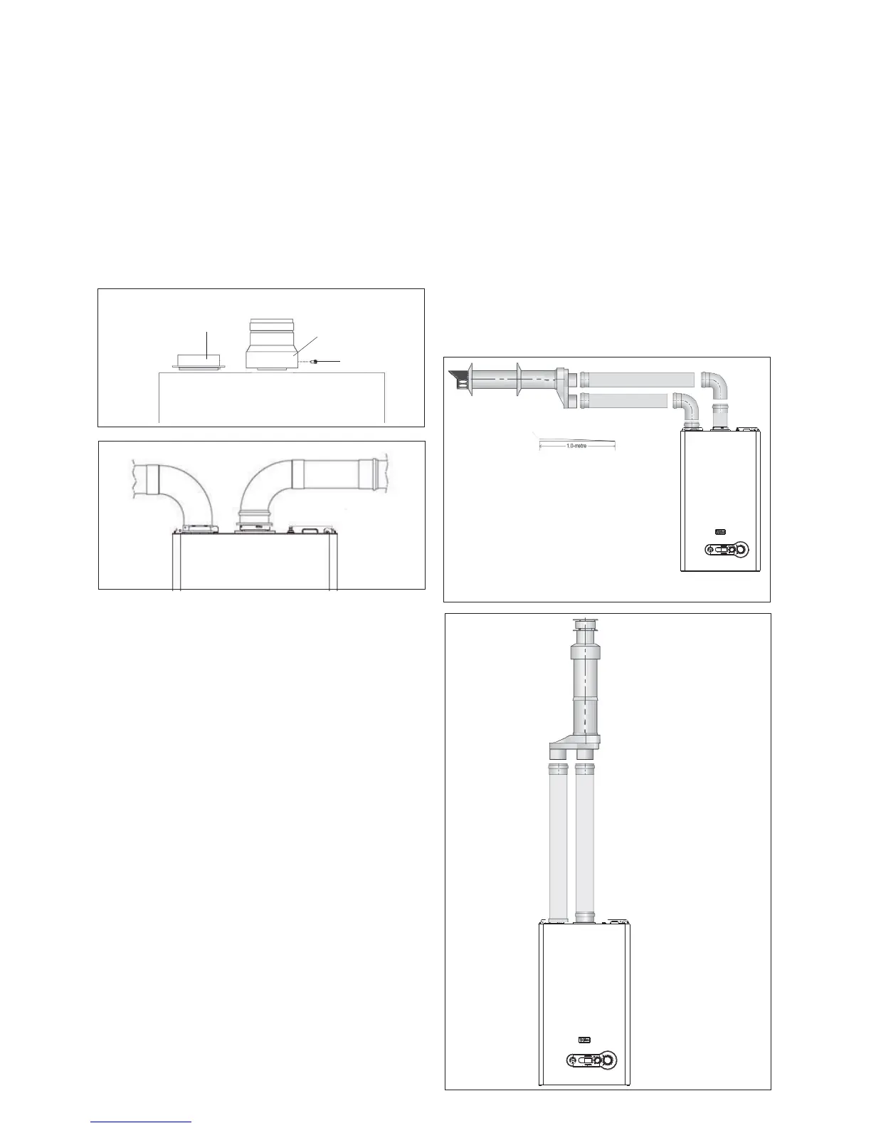
HORIZONTAL TERMINATION (fi g. 21)
The twin fl ue system must be converted to the dedicated con-
centric fl ue kit for termination.
• The horizontal terminal is supplied with a built-in converter
box and cannot be shortened.
• A 130mm hole is required for the passage of the concentric
terminal through the wall.
• The air inlet pipe must always be level with or below, that of
the exhaust pipe.
Depending on site conditions it may be preferable to install the
terminal assembly prior to fi tting the twin fl ue pipes.
Mark and drill a level 130mm hole for the passage of the horizontal
fl ue terminal. Insert the terminal assembly into the fl ue hole.
Push-fi t the twin fl ue pipes onto the concentric to twin converter
box ensuring that the exhaust pipe connects to the exhaust
connection on the concentric to twin converter.
If necessary cut the plain ends (male) of the twin fl ue pipes to
allow connection to the concentric to twin converter.
NOTE
Before cutting twin fl ue pipes ensure allowances have been
made for connection onto the previous piece and onto the
concentric to twin converter. The last twin fl ue pipes must be
pushed 50mm onto the male spigots of the concentric to twin
converter.
NOTE
Seal the fl ue terminal assembly to the wall using cement or a
suitable alternative that will provide satisfactory weatherproof-
ing. The interior and exterior trim can now be fi tted.
VERTICAL TERMINATION (fi g. 22)
The twin fl ue system must be converted to the dedicated con-
centric fl ue kit for termination.
• The vertical terminal is supplied with a built-in converter box
and cannot be shortened.
INSTALLATION OF TWIN ADAPTOR KIT (fi g. 19 & 20)
• Insert the exhaust connection manifold (A) onto the appliance
fl ue outlet.
• Remove the blanking plate (located to the left of the appliance
fl ue outlet) and – using the same screws – install the air inlet
plate (B).
• Using the hole in the exhaust connection manifold as a guide,
drill a 3mm hole in the appliance fl ue spigot and secure the
exhaust manifold connection to the fl ue spigot using the screw
provided (C).
• Using the two holes in the air inlet plate as a guide, drill a
3mm hole in each and secure the air inlet pipe/bend using
the screws provided.
The twin fl ue pipes extensions and accessories can now be
installed by pushing together (the plain end of each extension
or bend should be pushed approximately 50mm into the female
socket of the previous piece).
B
A
C
Fig. 20
• A 130mm hole is required for the passage of the concentric
terminal through the ceiling and/or roof.
Depending on site conditions it may be preferable to install the
terminal assembly prior to fi tting the twin fl ue pipes.
Fit the appropriate fl ashing plate to the roof and insert the ver-
tical fl ue terminal through the fl ashing plate from the outside,
ensuring that the collar on the fl ue terminal fi ts over the fl ashing.
Push-fi t the twin fl ue pipes onto the concentric to twin converter
ensuring that the exhaust pipe connects to the exhaust con-
nection on the concentric to twin converter.
If necessary cut the plain ends (male) of the twin fl ue pipes to
allow connection to the concentric to twin converter.
NOTE
• Before cutting twin fl ue pipes ensure allowances have been
made for connection onto the previous piece and onto the
concentric to twin converter. The last twin fl ue pipes must be
pushed 50mm onto the male spigots of the concentric to twin
converter.
• You must ensure that the entire fl ue system is properly sup-
ported and connected.
• Ensure that any horizontal sections of pipe have a fall of be-
tween 1 & 3º towards the appliance (1º =17mm per 1000mm).
Fig. 21
Fig. 22
1-deg = 17mm