15
IMPORTANT
The vertical fl ue terminal is 1.0 metre in length and cannot be
cut; therefore it may be necessary to adjust the height of the
appliance to suit or use a suitable extension.
Connect the vertical fl ue assembly to the boiler fl ue spigot us-
ing the 100mm clip, gasket & screws (supplied), ensuring the
correct seal is made. The fl ue support bracket (supplied with
the vertical fl ue kit) can now be fi tted.
If the vertical fl ue requires extension/s or additional bend/s,
connect the required number of fl ue extensions or bends (up
to the maximum equivalent fl ue length) between the boiler and
vertical fl ue assembly (see fi g. 22).
Ensure that any horizontal sections of the fl ue system have a
minimum 1º; maximum 3º fall back to the boiler (1º = 17mm
per 1000mm).
NOTE
When cutting an extension to the required length, you must
ensure that the excess is cut from the plain end of the exten-
sion. Remove any burrs, and check that any seals are located
properly.
You must ensure that the entire fl ue system is properly sup-
ported and connected.
4.5.3 TWIN FLUE SYSTEM
The Vokèra twin fl ue system enables greater fl ue distances
to be achieved than that of a concentric fl ue system. It can be
used for horizontal or vertical applications, however the twin
fl ue system must be converted to the dedicated concentric
fl ue kit for termination. It is essential that the installation of the
twin fl ue system be carried out in strict accordance with these
instructions.
GUIDANCE NOTES ON TWIN FLUE INSTALLATION
• The fl ue must have a have a minimum 1º; maximum 3º (1º =
17mm per 1000mm) fall back to the appliance to allow any
condensate that may form in the fl ue system to drain via the
condensate drain. Consideration must also be given to the fact
that there is the possibility of a small amount of condensate
dripping from the terminal.
• Ensure that the entire fl ue system is adequately supported,
use at least one bracket for each extension.
• As the exhaust outlet pipe can reach very high temperatures
it must be protected to prevent persons touching the hot
surface.
• The condensate drain pipe must be connected in accordance
with building regulations.
Reduction for bends
Bend Reduction in maximum fl ue length for each bend
45º bend 1.0 metre
90º bend 1.5 metre
Twin fl ue accessories
Part No. Description Length
0225805 Horizontal fl ue terminal 1.0 metre
0225810 Vertical fl ue terminal 1.0 metre
359 Twin adapter kit N/A
531 Pitched roof fl ashing plate N/A
532 Flat roof fl ashing plate N/A
0225815 Condensate drain kit N/A
0225820 0.25m extension (pair) 250mm
0225825 0.5m extension (pair) 500mm
0225830 1.0m extension (pair) 1000mm
0225835 2.0m extension (pair) 2000mm
0225840 45º bend (pair) N/A
0225845 90º bend (pair) N/A
0225850 Twin bracket (5) N/A
0225855 Single bracket (5) N/A
MOUNTING THE BOILER
The fi xing holes for the wall-mounting bracket should now be
drilled and plugged, an appropriate type and quantity of fi xing
should be used to ensure that the bracket is mounted securely.
Once the bracket has been secured to the wall, mount the ap-
pliance onto the bracket.
4.5.2 CONCENTRIC VERTICAL FLUE
The appliance can be used with either the Vokèra condensing
60/100mm concentric fl ue system or the optional 80/125mm
concentric fl ue system.
NOTE
These instructions relate only to the Vokèra condensing
60/100mm concentric fl ue system. For specifi c details on the
installation of the 80/125mm concentric fl ue system please refer
to the instructions supplied.
The vertical fl ue terminal can be connected directly to the ap-
pliance fl ue outlet. Alternatively, an extension or bend can be
connected to the appliance fl ue outlet if desired, however if
additional bends are fi tted, a reduction must be made to the
maximum fl ue length (see table below).
Reduction for bends
Bend Reduction in maximum fl ue length for each bend
45º bend 1.3 metre (60/100) - 1.0 metre (80/125)
90º bend 1.6 metre (60/100) - 1.5 metre (80/125)
Vertical fl ue terminal and accessories
Part No. Description Length
29450122 Vertical fl ue terminal 1000mm
531 Pitched roof fl ashing plate N/A
532 Flat roof fl ashing plate N/A
29450123 90-degree bend N/A
29450124 45-degree bends (pair) N/A
29450125 500mm extension 500mm
29450126 1000mm extension 1000mm
29450127 2000mm extension 2000mm
29450128 Telescopic extension 372/519mm
529 Wall bracket pack (5) 208mm
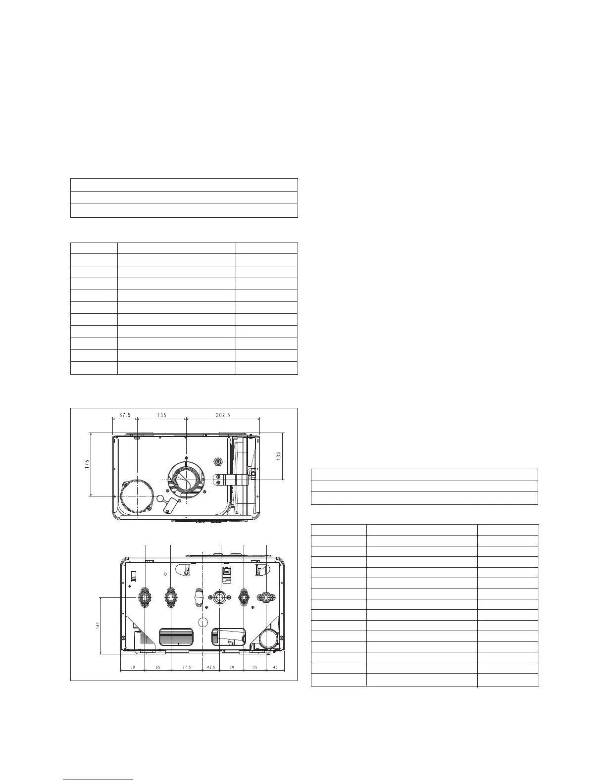
Using the dimensions given in fi g. 13 as a reference, mark and
cut a 125mm hole in the ceiling and/or roof.
Fig. 18
Fit the appropriate fl ashing plate to the roof and insert the ver-
tical fl ue terminal through the fl ashing plate from the outside,
ensuring that the collar on the fl ue terminal fi ts over the fl ashing.
The fi xing holes for the wall-mounting bracket should now be
drilled and plugged, an ‘appropriate type and quantity of fi xing
should be used to ensure that the bracket is mounted securely.
Once the bracket has been secured to the wall, mount the ap-
pliance onto the bracket.
RTN
FLOW GAS HOT COLD