14
Fig.13a
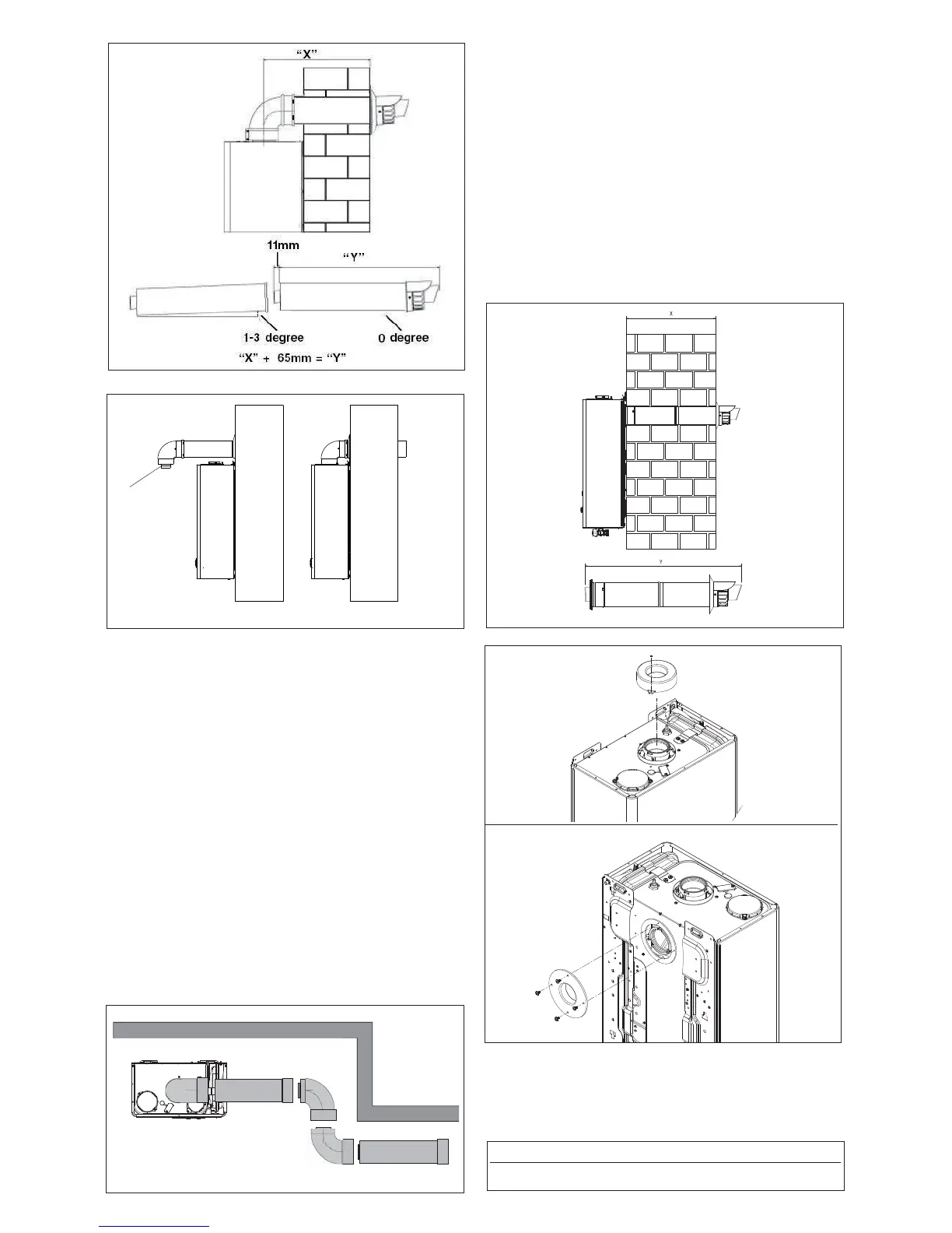
EXTENDING THE FLUE
Connect the bend – supplied with the terminal kit – to the top
of the boiler using clamp (supplied) see fi g. 12. The additional
bends & extensions have push-fi t connections, care should be
taken to ensure that the correct seal is made when assembling
the fl ue system. Connect the required number of fl ue exten-
sions or bends (up to the maximum equivalent fl ue length) to
the fl ue terminal (see fi g. 12-22). The fl ue system should have
a minimum of 1º; maximum of 3º rise from the boiler to outside,
to ensure any condense fl uid that forms, is allowed to drain
back to the appliance.
NOTE
When cutting an extension to the required length, you must
ensure that the excess is cut from the plain end of the extension
(see fi g. 12-22). Remove any burrs, and check that all seals are
located properly. You must ensure that the entire fl ue system is
properly supported and connected. Seal the fl ue assembly to
the wall using cement or a suitable alternative that will provide
satisfactory weatherproofi ng. The interior and exterior trim can
now be fi tted.
Fig. 14
A
Fig. 13
4.5.1.2 FITTING THE REAR FLUE (fi g. 15) (rear fl ue outlet
only)
Using the template provided, mark and drill a 125mm hole
for the passage of the fl ue pipe. The hole should be drilled
LEVEL to ensure any condense fl uid that forms, is allowed
to drain back to the appliance. The fi xing holes for the wall-
mounting bracket should now be drilled and plugged, an ap-
propriate type and quantity of fi xing should be used to ensure
that the bracket is mounted securely. Once the bracket has
been secured to the wall, attach the rear fl ue terminal to the
appliance (using the previously retained screws) and fi x the
telescopic terminal to the correct length (wall thickness) en-
suring that the terminal will protrude through the wall by the
correct distance. At this point, lift the appliance and carefully
insert the terminal into and through the wall, ensuring that the
holes in the appliance back frame are aligned with the studs
on the wall bracket.
Fig.15
Fig.17
Using the screws and washers provided, secure the applian-
ce onto the wall bracket and tighten with a suitable spanner.
Seal the fl ue assembly to the wall using cement or a suitable
alternative that will provide satisfactory weatherproofi ng. The
exterior wall trim can now be fi tted.
Fig.16
Part No. Description Length
29450133 Rear fl ue terminal 825mm