29
7.10.1 CHECKING THE FAN SPEED
Locate the CO button (see Fig 44 pos SW1).
Select the main selector switch to the ON position, press the
CO button once, the display will then scroll through the fan
speeds along with the relevant icon.
7.10.2 THERMOREGULATION
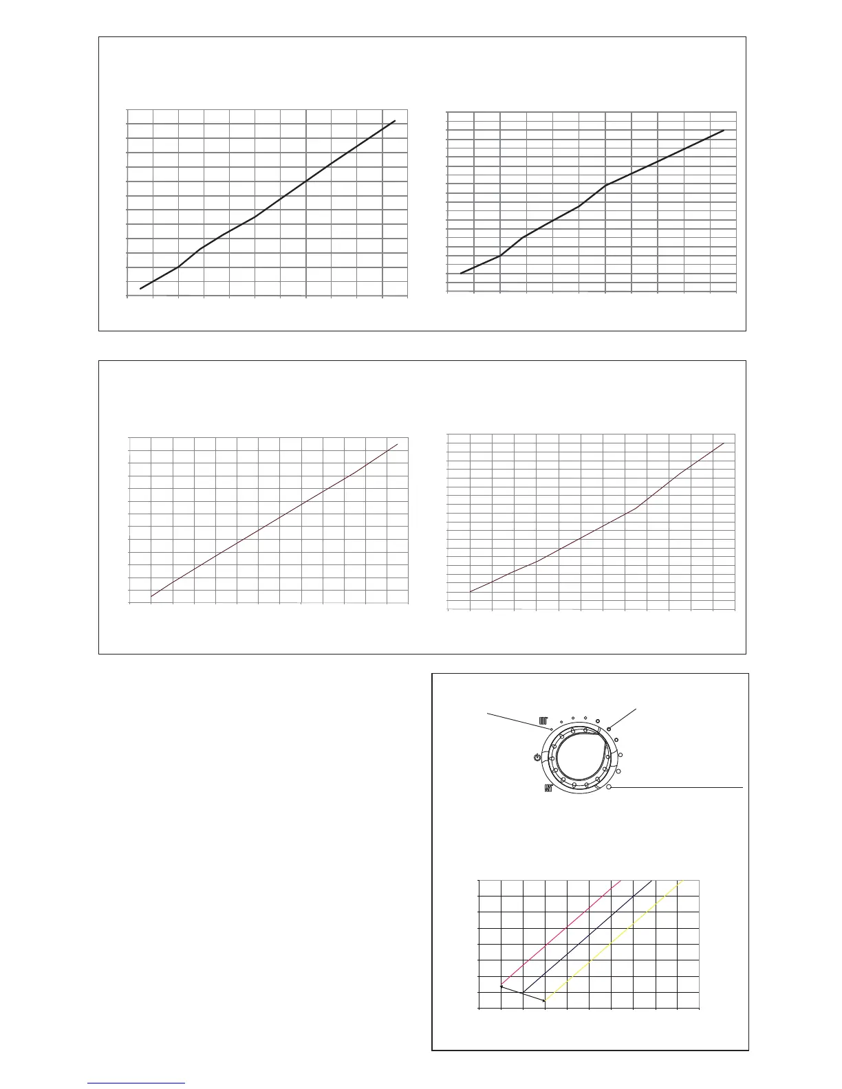
To set the temperature regulation curve, locate potentiometer
(P3). By turning (P3), the curve is shown on the LCD display.
The user can adjust the temperature of the heating system
indirectly by changing the required room temperature from
between 15°C & 25°C, this will allow the PCB to recalculate
the system temperature required, the default temperature for
calculating the curve is 20°C.
The graph below can be used to determine the correct curve
setting.
REFERENCE
TEMPERATURE 15 °C
REFERENCE
TEMPERATURE 20 °C
REFERENCE
TEMPERATURE 25 °C
20 °C
25 ° C
15 °C
10
20
30
40
50
60
70
80
90
-20-15-10-5051015202530
ROOM TEMPERATURE CURVE OFFSET
DELIVERY TEMPERATURE (°C)
EXTERNAL TEMPERATURE (°C)
Fig. 46
The boiler is supplied with the adjustments shown in the table. Depending on plant engineering requirements or regional fl ue gas emission limits it is, however,
possible to modify this value, referring to the graphs below.
COs.a. curve (Qnheating)
Heat output (kW)
HTG curve (Qnheating)
Heat output (kW)
Fan rotations (rpm)
CO emissions s.a. (p.p.m.)
Compact 29A
The boiler is supplied with the adjustments shown in the table. Depending on plant engineering requirements or regional fl ue gas emission limits it is, however,
possible to modify this value, referring to the graphs below.