40
Measuringalternatingcurrentswith400Hzlow-passlter
The current clamp comes with a 400 Hz software low-pass lter which can be switched on
when needed.
Follow the steps below to measure an alternating current with the low-pass lter.
• Turn on the product using the rotary switch and select the 2A
, 20A or 100A
measurement range.
• Press and hold the SELECT/V.F.C button (4) for approx. 2 seconds to enable the low-pass
lter. You will hear 3 beep tones and < UFC > will be briey displayed on the LCD display.
< VFC > (D) will then be displayed on the LCD.
• Proceed with the measurement according to steps 3 to 5 in "Measuring alternating currents
(A
)".
• To disable the low-pass lter, press and hold the SELECT/V.F.C button for approx. 2
seconds. You will hear a beep tone and < End > will be briey displayed on the LCD display.
Measuring direct currents (A
)
• Turn on the product using the rotary switch and select the 2A
, 20A or 100A
measurement range. Briey press the SELECT/V.F.C button (4) to switch to the DC
measurement range. < DC > and < A > appear on the display.
• Due to the high sensitivity and the ambient magnetic eld
(e.g. the earth's magnetic eld), a small current will always
be displayed when the current clamp is closed and in the
direct current measurement range. Manually reset the display
to zero immediately before each measurement or when the
cable is changed.
• Set the display to zero without a conductor and when the
clamp is closed by briey pressing the ZERO button (9). The
zero reset is conrmed by a beep tone and < ZERO > will
appear on the LCD display. Briey pressing the ZERO button
will reset the display to zero again. To disable this function, press and hold the ZERO button
for approx. 2 seconds. The < ZERO > symbol disappears. This will take you back to the
normal measuring mode without the zero reset.
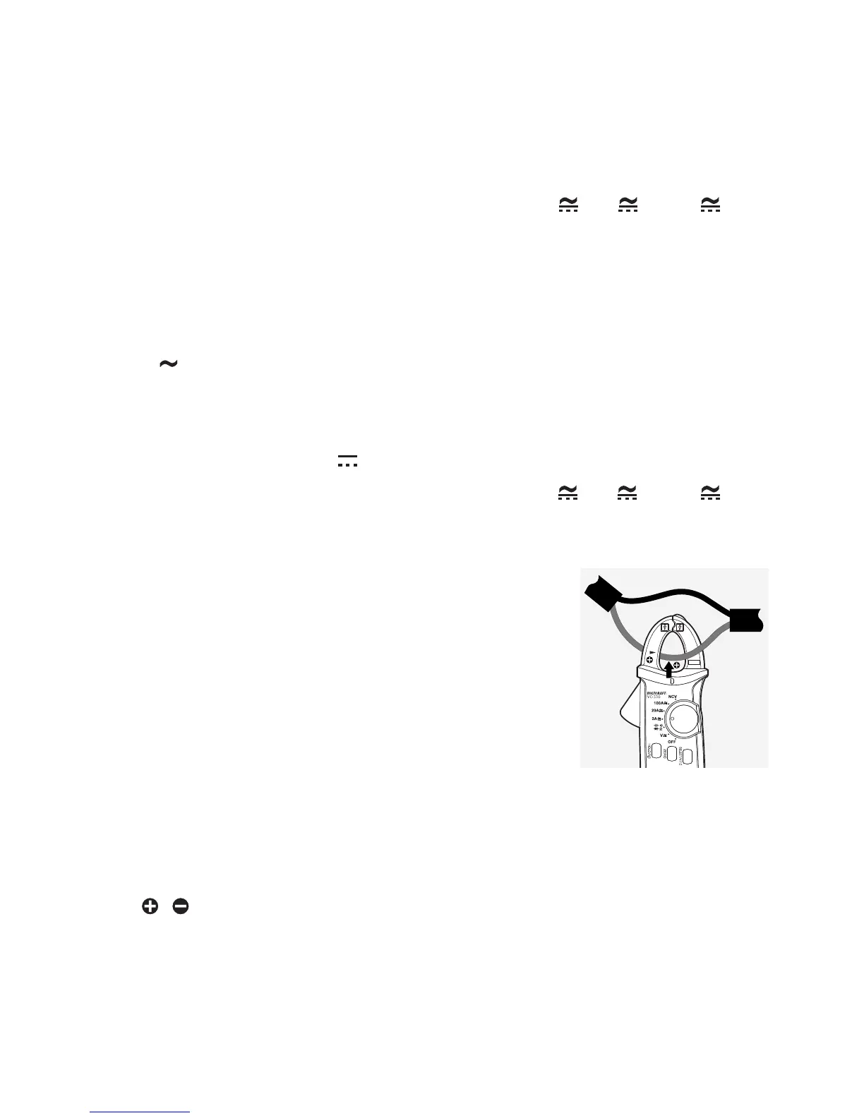
• Always ensure the correct polarity of the current clamp for direct current measurements. The
/ polarity symbols are located on the front and back of the current clamp. The cable
from the current source (+) must run from the front through the current clamp to the load
(gure 3).
CAT II
600V
CAT III
300V
100A