41
• Press the clamp opening lever (11) to open the current clamp. Surround the conductor that
you wish to measure and close the current clamp. Position the conductor in the middle
between the two triangular position symbols on the clamp.
• The measured current is shown on the LCD display.
A minus "-" symbol before the measured value indicates that the current ows in the
opposite direction (or the current clamp terminals have been reversed).
• After completing the measurement, remove the current clamp from the measured object and
turn off the device.
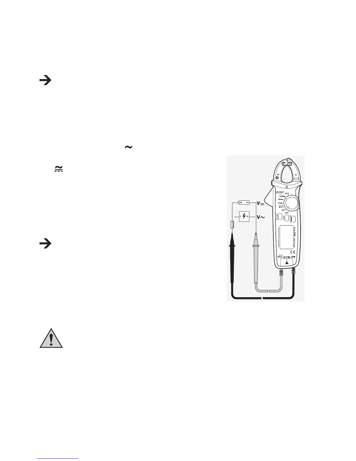
c) Measuring voltages "V"
Measuring "AC" voltages (V )
1. Turn on the device and select the measurement range
V
. < AC > and < V > appear on the display.
2. Insert the red test lead into the V socket (8) and the black
test lead into the COM socket (7) (gure 4).
3. Connect both of the test leads to the measured object
(generator, mains voltage etc.).
4. The measured voltage is shown on the LCD display.
The "V DC/AC" voltage range has an input resistance of
≥10 MOhm.
5. After completing the measurement, remove the current
clamp from the measured object and turn off the device.
Measuringalternatingvoltageswith400Hzlow-passlter
The current clamp comes with a 400 Hz software low-pass lter
which can be switched on when needed.
Never use the low-pass lter option to check the presence of dangerous
voltages! The voltages present may be higher than indicated on the device.
Alwayscarryoutavoltagemeasurementwithoutthelterrsttodetectany
dangerous voltages.
Follow the steps below to measure an alternating voltage with the low-pass lter:
CAT II
600V
CAT III
300V
100A