Electrochemical corrosion
101
Checking galvanic electricity,
calomel electrode
Connect the calomel electrode, special tool 885156-0
to the Digital probe tester, special tool 9988452-0
measurement cable.
Connect the probe tester tip to a good ground connec-
tion. Set the tester for DC measurement.
Carefully remove the protective sleeve from the probe
tip. The protective sleeve is filled with a saturated salt
solution (NaCI). Dry the tip with a clean paper tissue
or equivalent after measurement and before putting it
back.
Dip the electrode in water approximately 30 cm (12")
from the propeller and propeller shaft. The mea-
surement result is the mean value for the complete
shaft line. The result should lie between (minus) -900
mV and -1340 mV.
To check individual parts, move the electrode so that
the tip is directed towards the surface, approximate 5
mm (0.2") away from the surface where the part is fit-
ted.
The measurement result here should also lie between
–900 and –1340 mV.
If the result exceeds this (i.e. is a more positive value
such as –800), the proportion of “noble” metals such
as stainless steel, bronze etc., is too great for the
zinc anodes to overcome the corrosion current. The
anodes should be increased.
The result may also be from stray currents caused by
incorrect or incorrectly connected (+) cable or (+) ca-
bles exposed to bilge water.
There is overprotection if the digital tester gives a re-
sult less than –1340 mV. This could also be caused
by stray currents from separate ground cables for
VHF radio or other equipment fitted with separate
ground cables which are incorrectly connected.
The reason may also be that the anodes provide too
much protection current, e.g. magnesium anodes in
salt water.
Checking for leakages from the
electrical system
A simple way of testing the boat’s electrical integrity
is to employ the following procedure:
First check that fuses and circuit breakers are fitted
and intact, that the battery main switches are on, and
that all other switches and appliances are off. Theoret-
ically, there should be no current flowing from the bat-
tery. Any flow will indicate a leak.
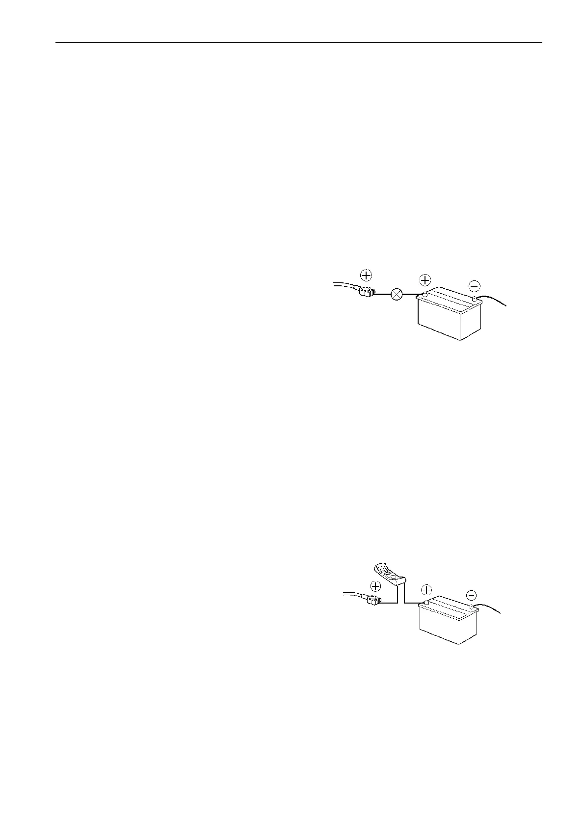
1. To check if any current is leaking.
Lift off the batteries positive battery terminal connec-
tor and place a 12-volt, 3W test lamp between the
positive terminal and the loosened connector. If there
is no leak, the lamp will fail to light. A faint glow indi-
cates a small leak, and a bright light means that you
have a more serious leak. You can also use a Voltme-
ter for this test. Note that some equipment may con-
sume current even when they are switched off (clock
or radio), which will cause the lamp to light. Such
equipment must be disconnected.
2. To check how much current that are flowing.
Use a multimeter, and set it to read ”DC Amps”. Con-
nect the red test lead to the battery positive terminal,
and the black lead to the loosened connector. The
meter will now show how much current is leaking. If
you do not get a reading, change to ’’DC mAmps’’
scale.
 Loading...