Electrical system
86
Calculating the cable area feeder lead
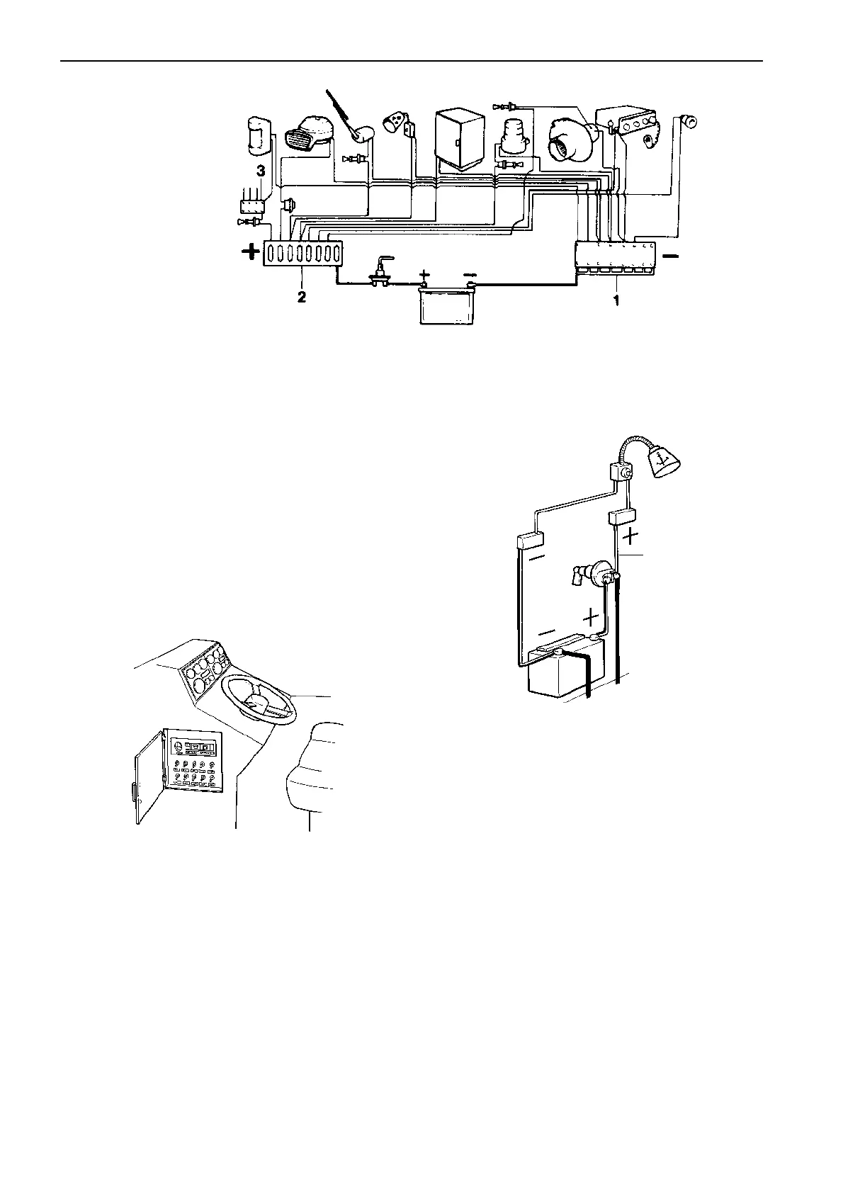
Position the electrical system control panel in a place
free from moisture with easy access and close to the
instrument panel.
If a 220 V system is installed, this area of the control
panel must be clearly identified.
NOTE! Make sure all components used are suitable
for the marine environment. Spray all electrical equip-
ment with a moisture- repellent spray.
Accessories
Please note that the length and the area of the feeder
cable (A) is dependent on how many accessories are
to be connected to it.
• Add up all accessories (power consumers)
• Measure the length of the feeder cable (A)
• See table on the next page. The table will give you
the feeder cable area.
Before installing extra accessories, such as naviga-
tion instruments, extra lighting, radio, depth sounder
etc., carefully calculate the total electrical power con-
sumption of these extras in order to be sure that the
charging capacity in the boat is sufficient.
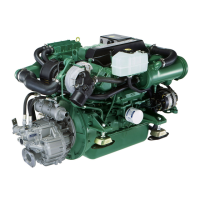
The above diagram indicates how this extra equip-
ment can be installed in the boat. Clamp the leads at
close intervals and preferably mark the leads at junc-
tion box (1 and 2) with the purpose of each lead, i.e.
communication radio, refrigerator, navigation lights
etc.
1 = Junction box for ground lead (–)
2 = Fuse box (+)
3 = Junction box, navigation lights
A