Controls
119
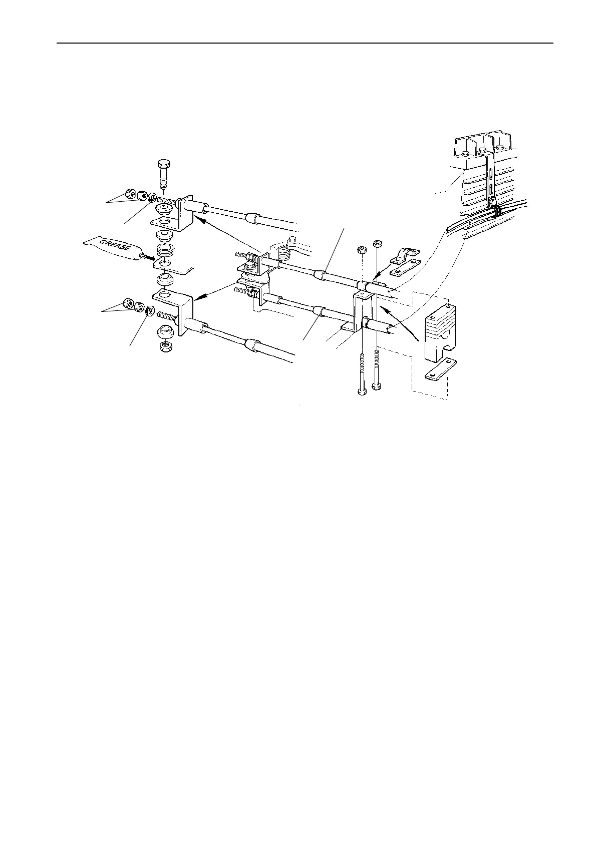
Connecting the speed control cable
A
B
A. Single station
B. Twin station (accessories)
2
2
1
1
To increase of the engine speed, the speed control
cable must have a pulling movement on all engines.
The speed control cable is connected at the fuel injec-
tion pump as shown in the figure below. Connections
should be made so as to obtain the largest possible
stroke on the control cable to provide the smoothest
control procedure. The pump lever, however, must al-
ways be in contact with the full speed stop at full
throttle.
When double cables are connected as shown in fig-
ure, the cables run freely through their attachments to
the pump lever.
NOTE! The nuts on the ends of the cables must be
locked against each other when the pump lever and
control levers are simultaneously at their idling and
neutral positions respectively.
NOTE! There shall be a clearance of 2 mm (0.1")
between O-ring (2) and lock nuts (1).



 To Next Page