General arrangement and planning
27
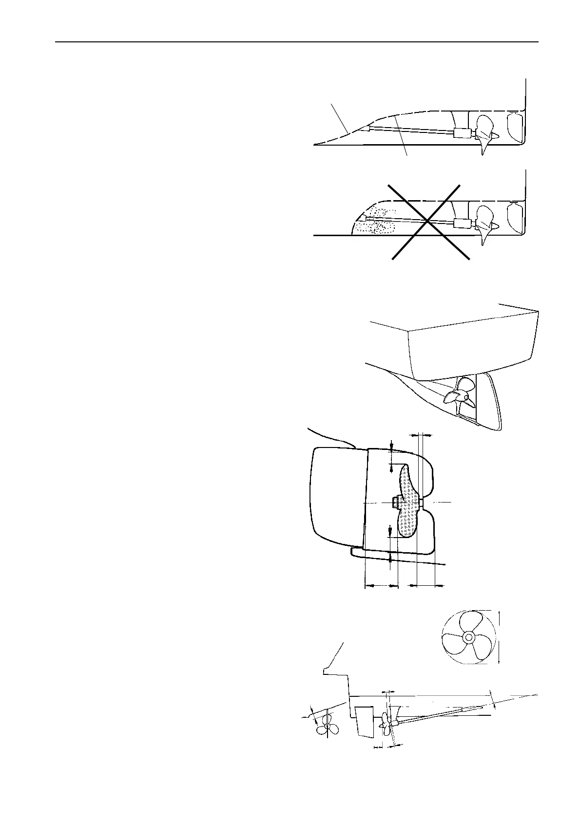
Check the shaft angle. If the shaft angle exceeds 12°,
the use of a smaller propeller should be considered.
This can be compensated by more blades or larger
blade area.
The keel or the propeller shaft brackets in front of the
propeller should have a profile creating a minimum of
drag and turbulence. Also the shape of a tunnel is
very important. A poor tunnel design can create a lot
of turbulence in the propeller and reduce the boat’s
buoyancy at the stern. It is vital that the radius (R1)
creating the entrance of the tunnel is large enough to
avoid turbulance into the propeller.
Ensure that there is sufficient space between the pro-
peller, hull, keel, skeg and the rudder. It should be
possible to move the propeller shaft at least 200 mm
(8") aft to allow the removal of the reverse gear or
coupling. Also make sure that any transverse bulk-
head does not impede its removal. Sufficient clear-
ance, approx. 1 x the shaft diameter, must be provid-
ed between the propeller and the stern bearing to pre-
vent the propeller from pressing against the stern
bearing. Allowance should also be made for rope cut-
ters if they are to be fitted. See figures on this page,
position (E).
∅∅
∅∅
∅
E
B
A
D
F
A
B
C
D
E
The minimum distances to the hull, keel, skeg and
rudder.
∅∅
∅∅
∅= Propeller diameter
A = 0.10 x
∅∅
∅∅
∅
B = 0.15 x
∅∅
∅∅
∅
C = 0.10 x
∅∅
∅∅
∅
D = 0.08 x
∅∅
∅∅
∅
E = Approx. 1 x shaft diameter
F = Shaft angle. Shaft angles exceeding 12° should
be avoided.
Example: The measurement (A) for a boat with a pro-
peller diameter 30" (762 mm) is 0.10 x 762 = 76 mm
(0.10 x 30" = 3") minimum.
The measurement (A) must never be less than 50 mm
(2"). For classification, the requirements of the re-
spective classification body must be followed.
R1
R2
Radius R1
≈ ≈
≈ ≈
≈ radius R2