General arrangement and planning
34
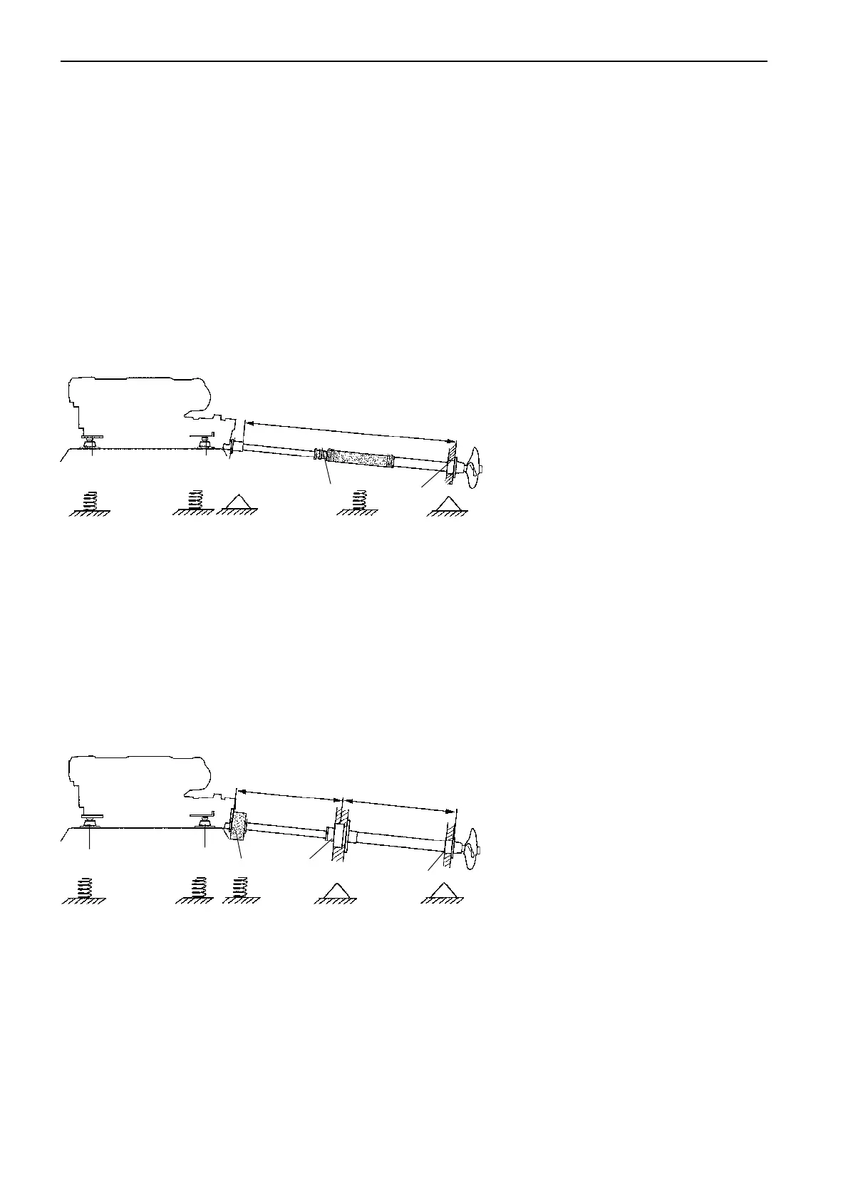
2. Engine with flexible mounts and
fixed shaft seal
1. Flexible engine mountings
2. Flexible shaft coupling
3. Fixed front stern bearing and shaft
seal
4. Water lubricated stern bearing
L. Distance between support points.
For calculation L max see page 42.
B. Distance reverse gear flange – sup-
port point.
Recommended B min is 6-10 x shaft
diameter.
B max is calculating in the same way
as L max.
1
1
2
3
B
L
4
Engine suspension vs
propeller shafting
NOTE! A flexible shaft coupling must never be fitted
together with a flexible mounted stuffing box. This can
cause vibration problems.
Stainless steel propeller shafts are available in differ-
ent diameters. The shaft dimension should be chosen
based on the engine power output, gear ratio, distance
between support points and propeller shaft material.
The following installation alternatives
and combinations are recommended:
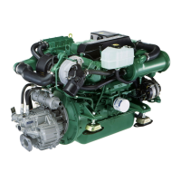
1. Engine with flexible mounts and
flexible shaft seal
In this case, a flexible shaft coupling
should not be installed.
1. Flexible engine mountings
2. Fixed shaft coupling
3. Flexible mounted shaft seal
4. Water lubricated stern bearing
L. Maximum distance between support
points. For calculation see page 42.
1
1
3
L
4
2