Engine foundation
40
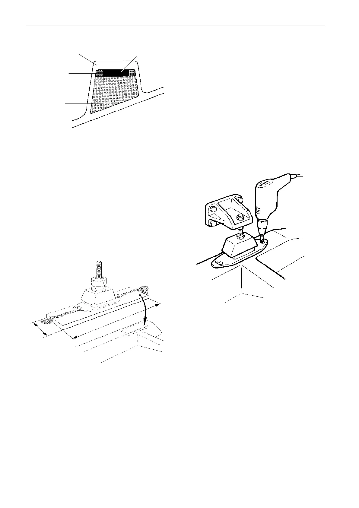
Drilling holes for engine
suspension
Bolt holes could, of course, be drilled and tapped
(threaded) by accurate measurements and fixtures at
other stages than outlined in this chapter. In serial
production and other frequent installations, more so-
phisticated methods may be desired and used.
NOTE! If the engine and engine mounts are used as a
drill rig, the holes to the engine mounts/rubber mounts
should be drilled in conjunction with installing the en-
gine in the boat.
See also chapter
Engine installation
.
L min
W min
Align the engine to the propeller shaft and mark up for
the holes of the engine mounts.
Drill and thread holes in bed and flat bars.
Recommended bolt diameter for Volvo Penta elastic
mounts:
Engine and reverse gear excl. HS63V (V-drive):
M12 alternatively 1/2"
HS63V (V-drive):
M16 alternatively 5/8"
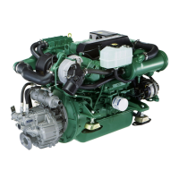
Fibreglass engine bed
A = Spacer material
B = Filler (rounding of corners)
C = Fibreglass, approx. 10–15 mm (0.4–0.6")
D = Flat bar, galvanized, approx. 10 mm (0.4")
A
B
C
D
•
•
•
To reduce noise and vibrations, the engine bed should
be filled. Make sure the material does not absorb wa-
ter.
Build up the engine bed with spacer material (A) so
that the underside of the engine mounts/ engine rub-
ber mounts almost rest against the bed. Divinylcell
can, for example, be used as spacer material. There
must be room for flat bars and fibreglass.
A 10–12 mm (0.4–0.5") thick galvanised flat bar with a
minimum length (L min) of 250 mm (10") and a mini-
mum width (W min) of 80 mm (3") should be built into
the engine bed.
Build in drain channels to allow water to drain to the
location of the bilge pump.