Propeller shaft systems
42
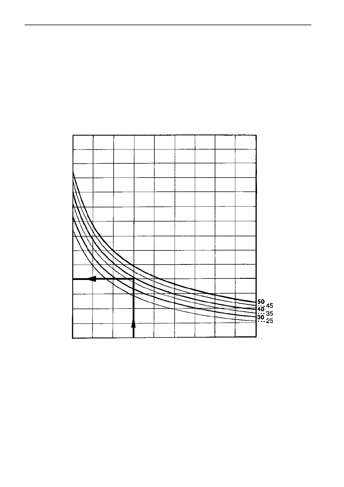
Example:
Engine: TAMD31P
Engine rpm: 3900
Gear ratio: 2.0:1
Shaft dia: 40 mm
Material: Stainless steel SIS 2324-02
Type of
installation: See figure,
Alternative 1
on
page 34.
1. Calculate the propeller shaft speed:
3900/2.0 = 2000 rpm (approx.).
2. Follow the diagram from the right hand side to the
40 mm diameter curve.
3. Follow the curve until it crosses the propeller shaft
speed line (2000 rpm).
4. From this point, draw a straight line out to the left
hand side (length in metres).
5. We get the distance of 1.8 metres (5.9 ft) between
the bearings.
Propeller shaft speed (rpm)
Distance
between
bearings
m (ft.)
Diameter
propeller shaft
(mm)
4.8
(15.7)
4.2
(13.8)
3.6
(11.8)
3.0
(9.8)
2.4
(7.9)
1.8
(5.9)
1.2
(3.9)
0.6
(2.0)
500 1000 1500 2000 2500 3000 3500 4000 4500 5000
Propeller shaft dimensions
and bearing distances
The propeller shaft will be subject to both bending and
torsional forces and must be dimensioned with regard
to this. Also a certain safety margin must also be ap-
plied. The maximum bearing distance has a major in-
fluence for the calculation of shaft dimensioning.
To determine the propeller shaft dimension and bear-
ing distance, use the diagram below, the Volvo Penta
computer program
MACP2
or consult the shaft suppli-
er.
The diagram here, for calculating the distance be-
tween the shaft bearings (or support bearings for the
propeller shaft), is based on the formula for critical
shaft speeds.
This diagram is valid for stainless steel SIS 2324-02
or equivalent.