Propeller shaft systems
46
Push the propeller shaft into place and align the shaft
and the stern bearing with the reverse gear’s output
shaft (reverse gear’s flange).
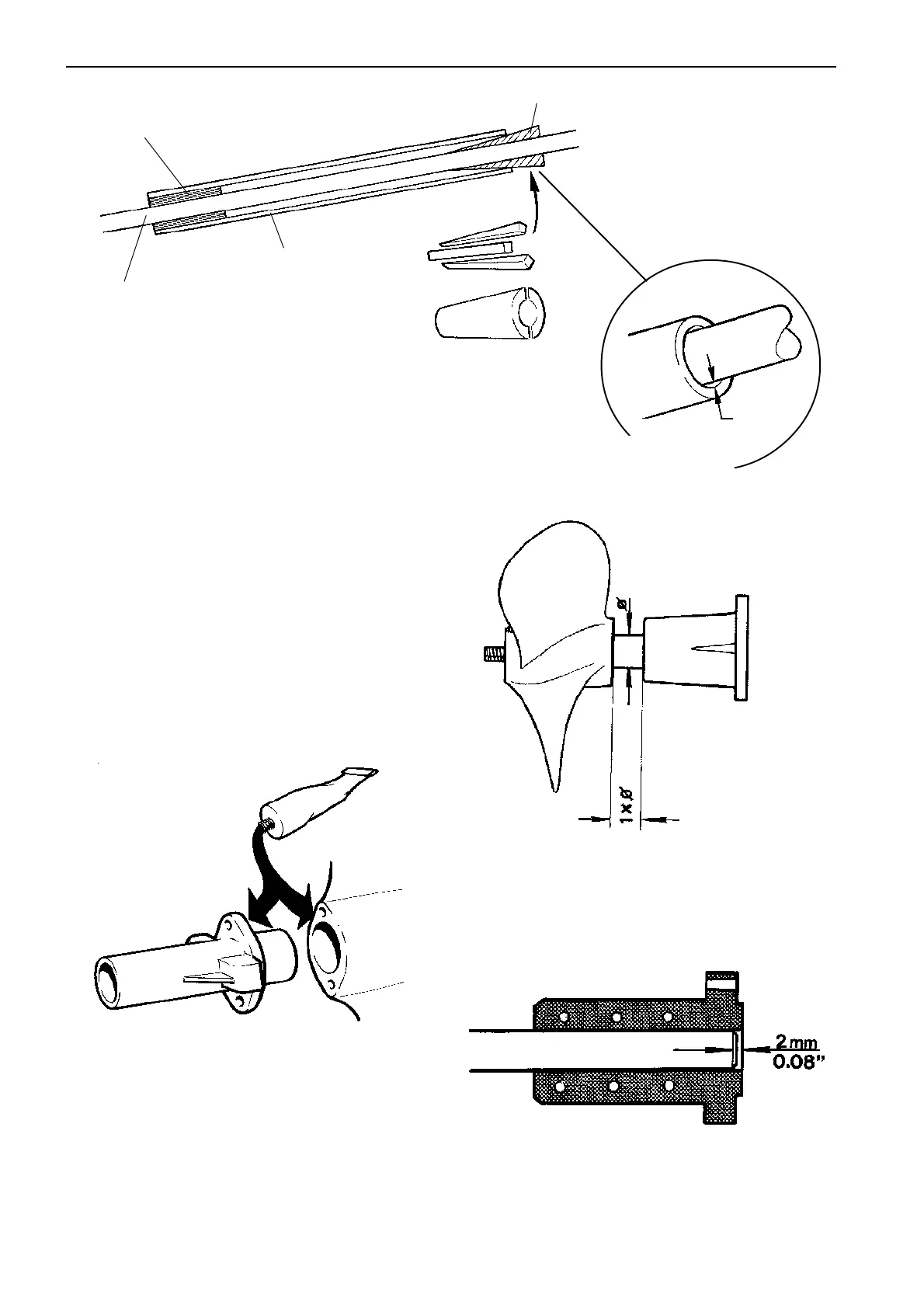
To prevent the shaft from bending in the stern shaft
tube, the shaft can be centred as follows:
• Install the shaft bearing (4).
• Centre the shaft (1) in the propeller shaft tube (2)
using wedge-formed guides (3).
• Check that the shaft is not bent in front of the
tube; support the shaft if necessary.
After alignment has carefully been done, the stern
bearing can be bolted or bonded in place.
1
2
3
4
4 mm
(0.16")
The clearance between the
propeller shaft and tube for a
flexible mounted engine should
be min. 4 mm (0.16").
If the stern bearing is to be bolted to the stern, the
contact surface for the bearing flange must be sanded
flat first. Apply sealing compound, e.g. silicon rubber,
and tighten the bolts holding the bearing.
NOTE! The alignment must be checked after bonding.
Cut the propeller shaft to the correct length. Remem-
ber that the distance between the rear edge of the
stern bearing and the propeller must be 1 x the shaft
diameter.
There must be a 2 mm (0.08") clearance between the
end of the shaft and the reverse gear’s flange (flexible
coupling).
 Loading...