WWW.VORONDESIGN.COM
CAD version: ERCF V2
136136
ARM GROUPS PREPARATION
MICROSWITCH WIRING HARNESS
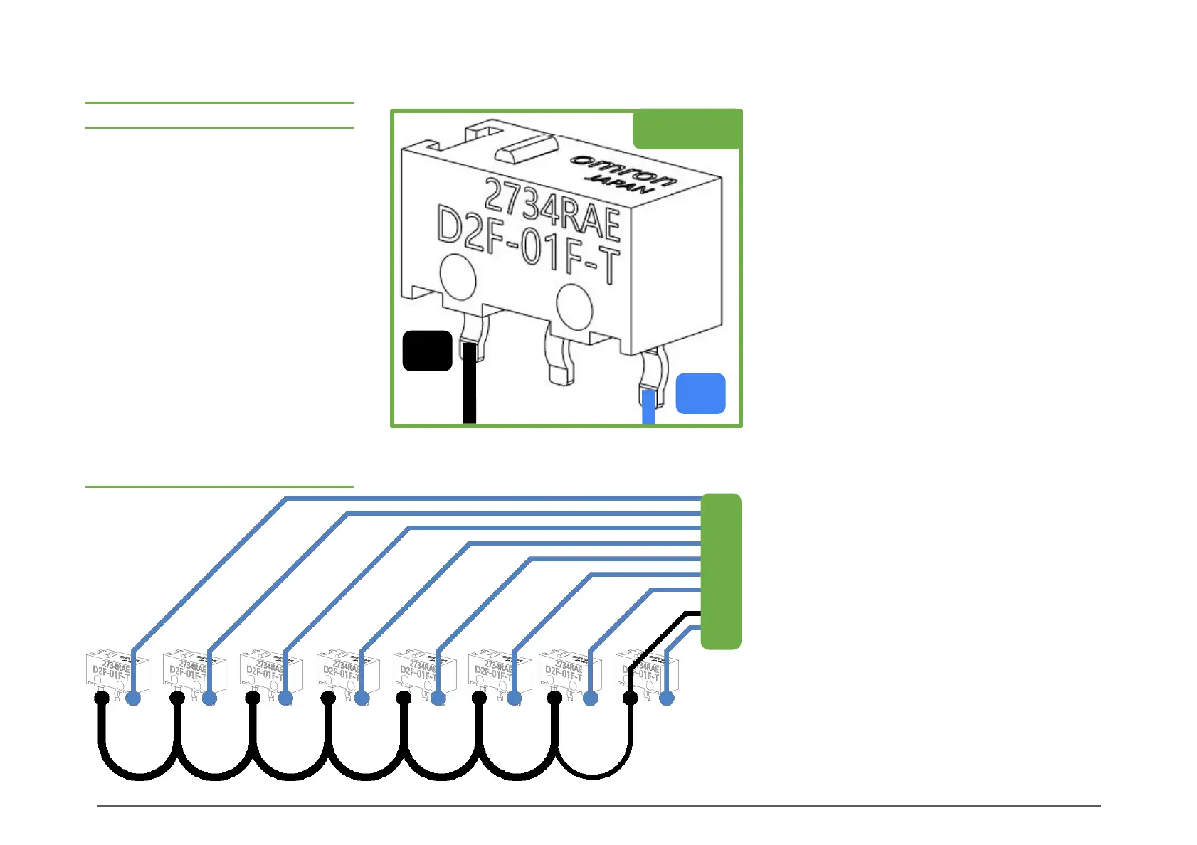
Microswitch
WIRING SENSORS
First, solder a wire to the Normally
Closed (NC) leg of each microswitch,
matching the length for each gate to the
table to the left.
Next, connect the Common (C) legs of
each neighboring switch with a piece of
wire 70mm long.
For the last microswitch in the chain,
solder an additional 120mm wire to the
Common leg, to feed to the MCU.
Your end result should look like the
second picture.
Make sure you follow the recommended
lengths to ensure that the switches are
not binding the Coupler_Block’s upper
sprung section.
This takes into account extra length so
you can trim the wire to be as tidy as
possible.
Use cable ties to keep bundles together.
To MCU
Gate NC Wire Length (mm)
0 50
1 73
2 96
3 119
4 142
5 175
6 198
7 221
8 244
9 265
10 288
11 301
12 324
13 347
14 370
NC
C