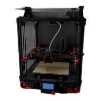
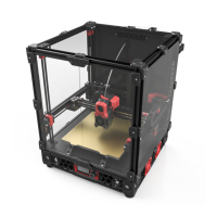
WWW.VORONDESIGN.COM
CAD version: ERCF V2
LOCAL MCU VS REMOTE MCU
When we say “local MCU” we mean a “buddy board” or other dedicated MCU that will
be mounted near the ERCF. Examples include the BTT MMB (preferred and shown in
this manual) and the EASY BRD. Skip to page 21 if you’re using a local MCU.
When we say “remote MCU” we mean the dedicated MCU(s) for your printer. It is
unusual to have enough spare motor, servo, and endstop ports to run an ERCF unless
you’re using a dual SKR board setup, but if that’s you, then you can save some money
on the buddy board by using this option.
PREPARING THE WIRES FOR REMOTE MCU
For an ease of installation, it is recommended to prepare the wiring before assembly.
There are two wire looms to do:
● One that goes from the connector plate to the selector motor
● One that goes from the connector plate to all the other components, namely the
endstop, the servo and the encoder
1818
WIRING (REMOTE MCU)
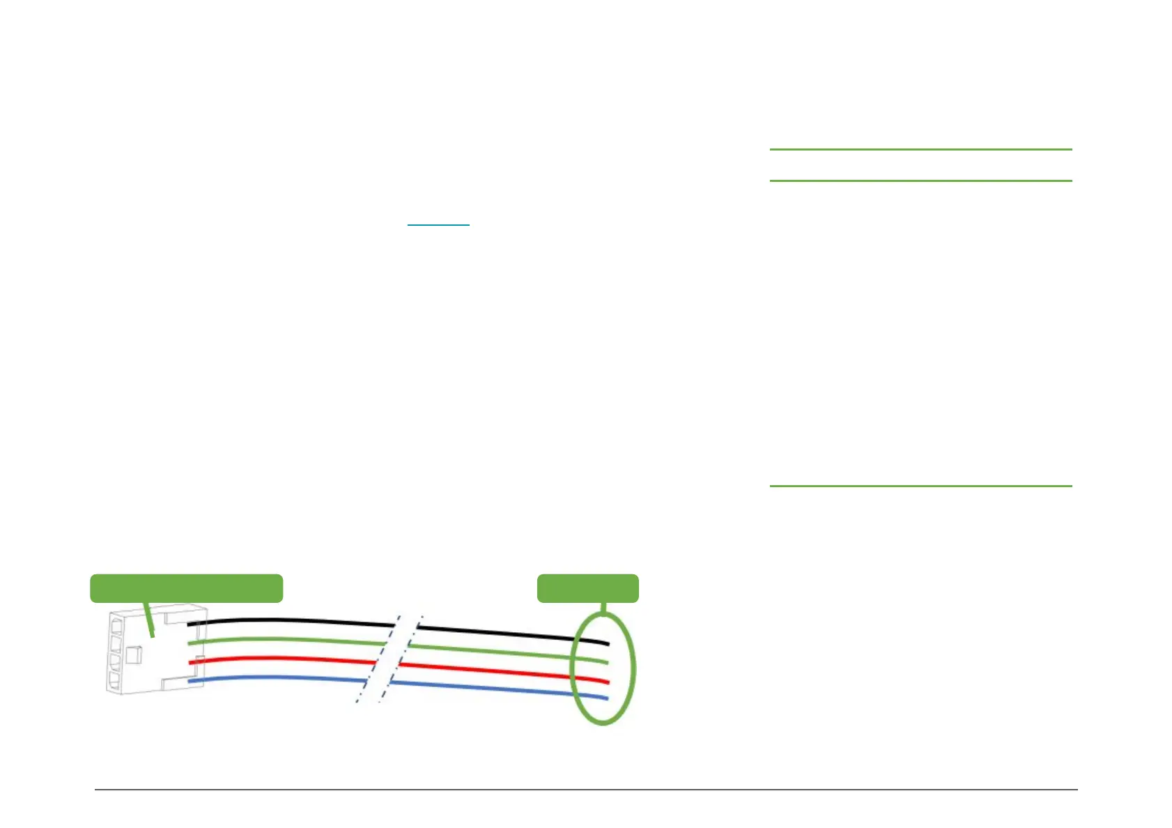
Molex Microfit 3 – 4 pins Free Ends
CONNECTION TO THE SELECTOR MOTOR
When using a remote MCU, it is recommended to
finish the selector motor connection later in the
assembly, for ease of assembly and to ensure the
crimps are done with the proper wire length
SELECTOR MOTOR WIRE FOR REMOTE MCU
Prepare the 4 wire selector motor cable as shown. Don’t crimp the free ends for now.
SELECTOR MOTOR WIRE
Channels Selector Motor Wire Length (mm)
N 175 + 25N
4 275
5 300
6 325
7 350
8 375
9 400
10 425
11 450
12 475
13 500
14 525
15 550
Wire Length Chart for remote MCU
All wire lengths in this manual
include approximately 25-50mm of
spare length for maintenance.