WWW.VORONDESIGN.COM
CAD version: ERCF V2
20
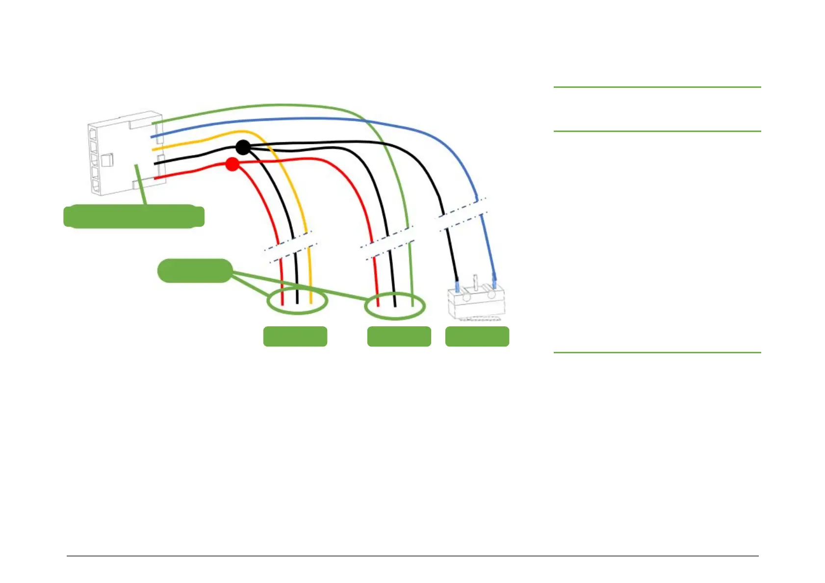
5 WIRE BUS
Prepare the 5 wire bus for the ERCF as shown. The GND is shared between the Servo, the Encoder and the Endstop. The +5V
is shared between the Servo and the Encoder.
To join the multiple GND//+5V lines, either crimp them together or make a splice prior to the crimp position.
Only the Endstop is directly connected to this wire bundle, typically by soldering the wires directly on the microswitch pins.
It is recommended to finish the Servo and Encoder connections later in the assembly, for ease of assembly and to ensure the
crimps are done with the proper wire length.
This should be a 6-wire bus with a wire to control the Apron LEDs, but we added them late in development for RC1 release!
20
WIRING (REMOTE MCU)
Free Ends
Molex Microfit 3 – 5 pins
Servo Encoder Endstop
SENSOR AND ENCODER WIRE BUS
Channels
Wire Length (mm)
Endstop Servo Encoder
N 60 35 + 5N 45 + 5N
4 60 55 65
5 60 60 70
6 60 65 75
7 60 70 80
8 60 75 85
9 60 80 90
10 60 85 95
11 60 90 100
12 60 95 105
13 60 100 110
14 60 105 115
15 60 110 120