IR610 high performance vector control frequency inverter user manual Chapter 8 Maintenance
- 165-
resistance, you shall disconnect the main circuit with the frequency inverter. Do not use the
insulation resistance meter to test the control circuit. It don’t have to do the high voltage test (It has
been done when the frequency inverter produced in factory.)
8.2 Wearing parts replacement
The vulnerable parts of the inverter mainly include cooling fans, electrolytic capacitors, relays, etc. The
life of the inverter is closely related to the environment and maintenance conditions used. Table 8-3 lists
the replacement time and causes of damage to the main components for reference. In addition, if
abnormality is found during maintenance, please replace it in time.
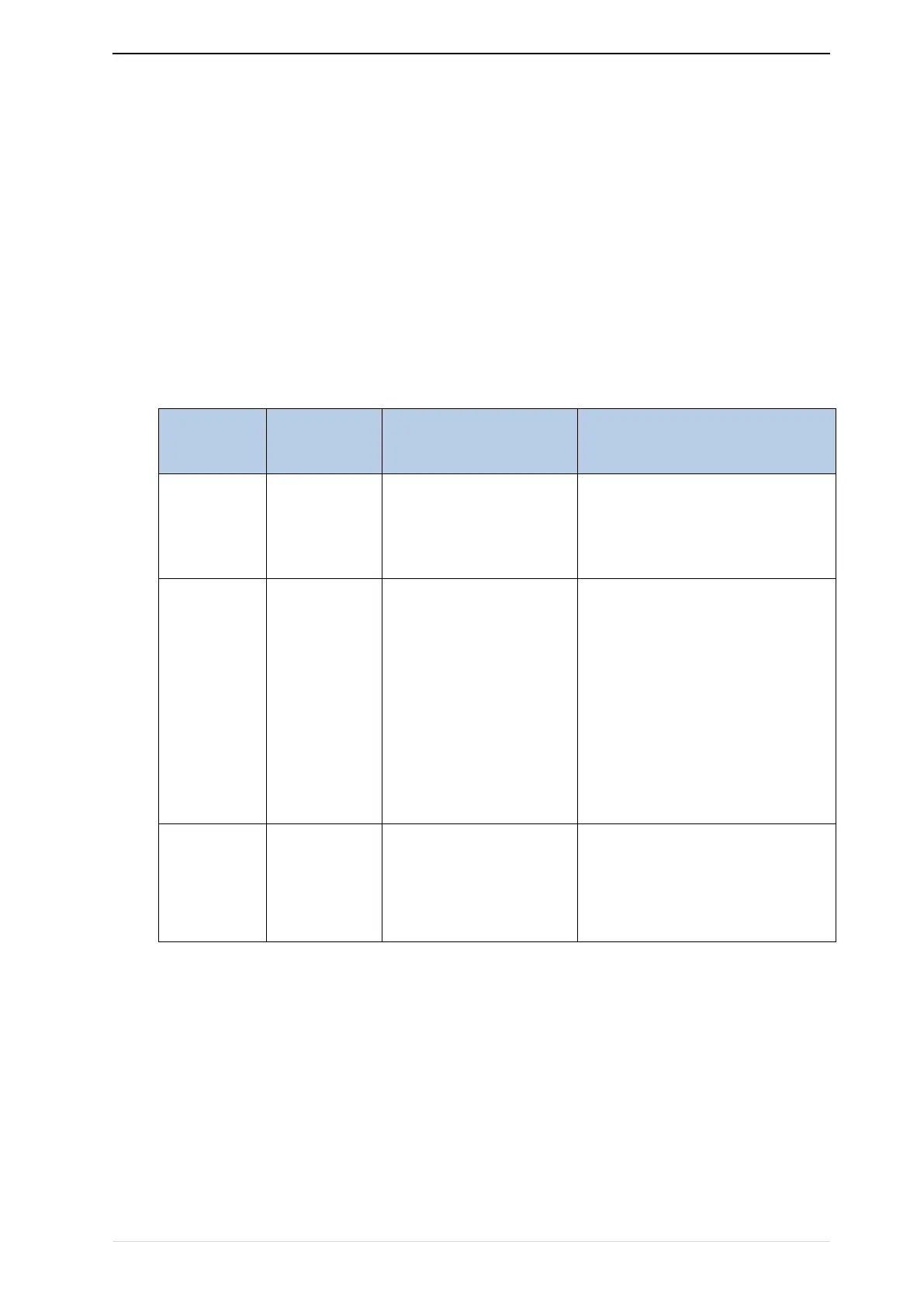
Table 8-3 Spared parts replacement time
Bearing wear, blade aging
1, the blade has cracks
2 abnormal vibration, excessive
noise
Poor input power quality,
high ambient
temperature, low air
pressure, frequent load
changes, electrolyte
aging
1, there is liquid leakage
2, the safety valve protrudes
3, the capacitance value is beyond
the allowable range
4, insulation resistance is abnormal
5, DC bus voltage fluctuations are
too large
Corrosion, dust affect
contact contact effect,
contact action is too
frequent
The user can refer to the accumulated power-on time and accumulated running time recorded by the
inverter, and combine the actual operating conditions and the external environment to determine the
replacement period.
1) Possible reasons for the damage of cooling fan: bearing wear and vane aging. Distinguish standard:
Any cracks in the fan vanes, any abnormal vibration sound during the starting of frequency inverter.
2) Possible reasons for the damage of filter electrolytic capacitor: poor quality of the input power supply,
the environment temperature is high, the load change frequently and the electrolyte aging. Distinguish
standard: Any leakage of its liquid, if the safety valve is protruding, electrostatic capacitance and
insulation resistance measurement.