Chapter 4 Operation and display IR610 high performance vector control frequency inverter user manual
- 37-
Chapter 4 Operation and display
4.1 LED Instruction of operation and display
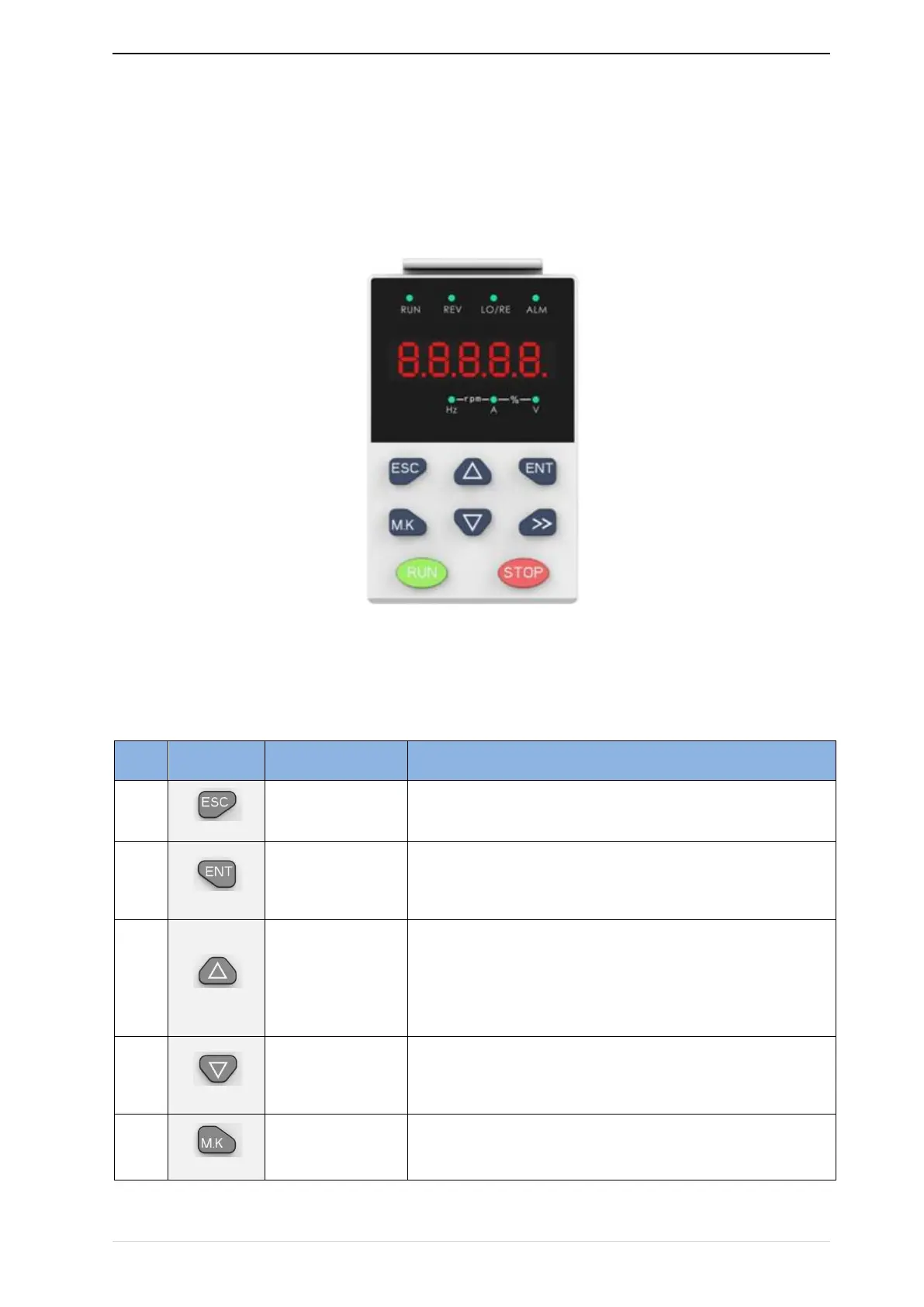
LED keyboard consists of 5 digital tubes, 7 lights, 8 keys and a potentiometer; can be used to set
the parameters, status monitoring and operation control, LED keyboard shape as shown in Figure 4-1:
Figure 4-1 Operating panel
Description of indicator
Table 4-1 The name and function of each part of the keyboard
•
Enter the menu interfaces level by level,
•
confirm the parameter setting and save to EEPROM
• The number indicated by the cursor increases by one.
• Next function code.
• Used to switch the left and right screens while in monitor mode