IR610 high performance vector control frequency inverter user manual Chapter 4 Operation and display
- 38 -
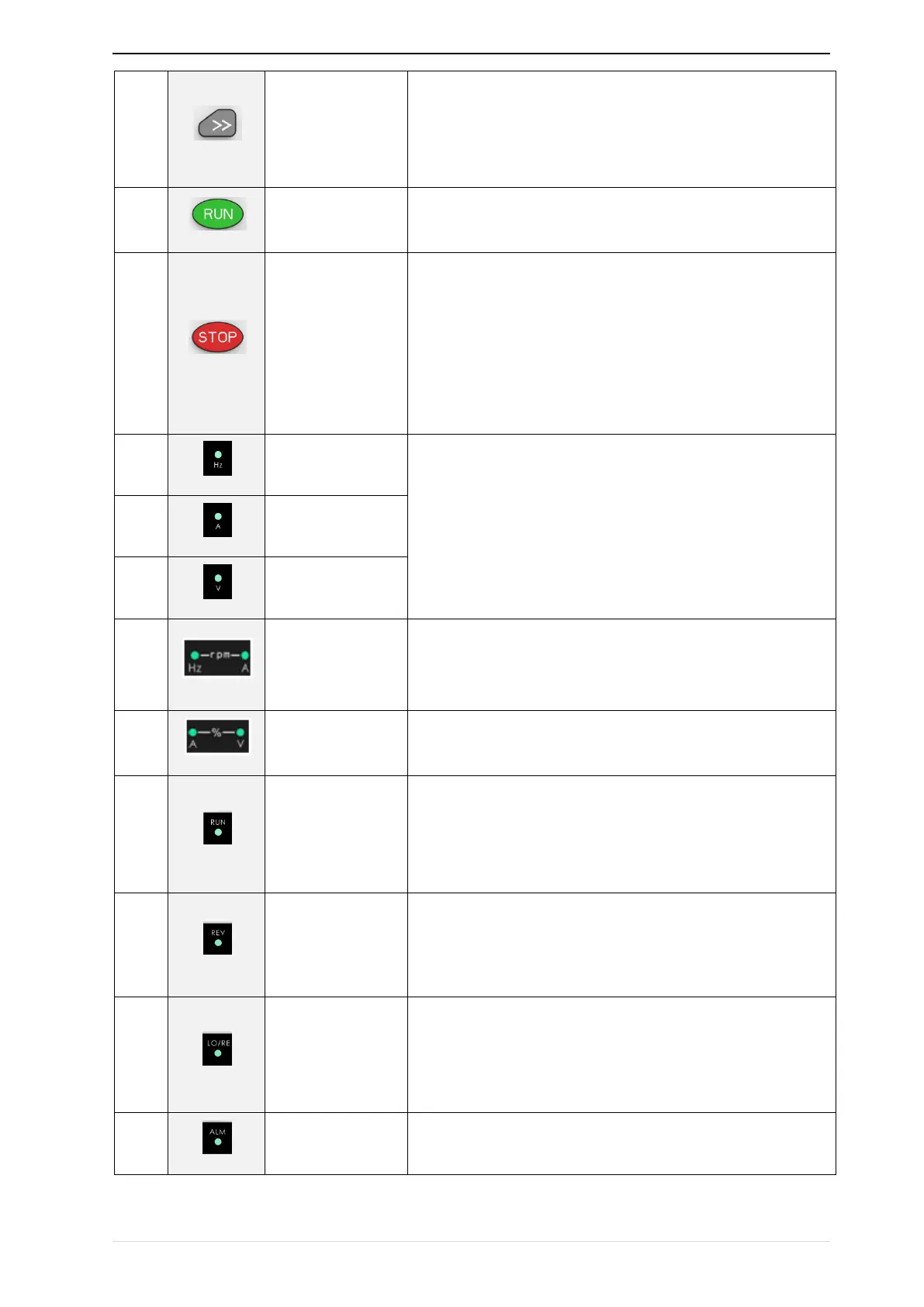
• Cursor shift.
• Monitor Status Displays the next monitor volume.
• Switch left and right screens.
Start the frequency inverter in the operation panel control
mode
• During operation, press to stop the operation (restricted by
parameter 21.03).
• In fault status, press this key to reset the fault.
·Indicate the digital display unit, all three lights off menas other
units
Indicator
light:HZ+A(rpm/min
ute)
When Hz" and "A" are lit at the same time, the unit of the currently
displayed parameter is "RPM PER MINUTE
When "A" and "V" are lit at the same time, the unit of the currently
displayed parameter is "percent".
• Off: indicates a stop condition.
• On: indicates inverter is running.·
Blinking: Deceleration stopped.
• Used to indicate the sign of the variable when the LED is
displaying one of the variables listed in 27.02;
• In other cases the sign of the output frequency is indicated.
• Off: The command source is the keyboard.
• On: The command source is terminal.
• Blinking: The command source is communication.
• When it is on, the drive is faulty.