Chapter3 product appearance and wiring IR610 high performance vector control frequency inverter user manual
- 28 -
If the cable between the inverter and the motor is too long, the higher harmonic leakage current of the
output end will produce by adverse impact on the inverter and the peripheral devices. It is suggested
that when the motor cable is longer than 100m, output AC reactor be installed. Refer to the following
table for the carrier frequency setting.
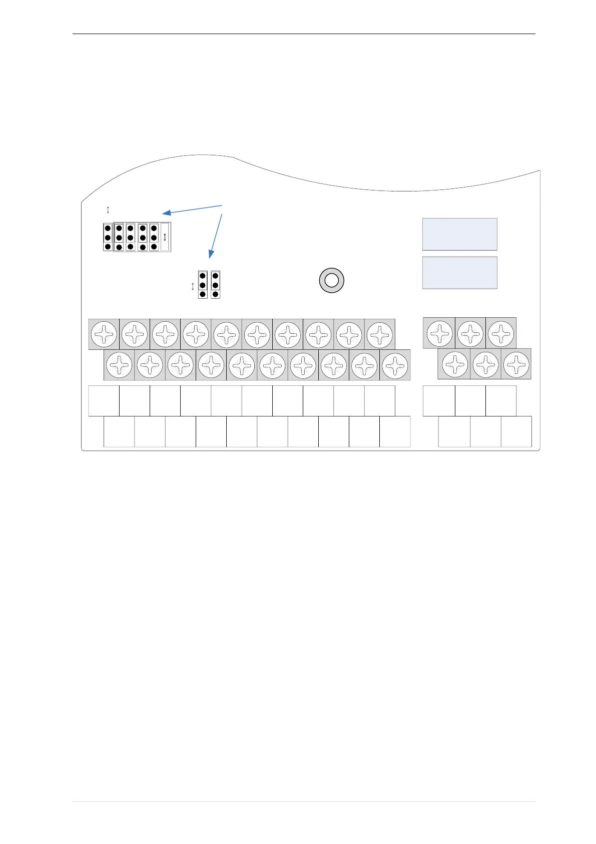
3.2.4Control Circuit Terminal