IR610 high performance vector control frequency inverter user manual Chapter3 Product appearance and wiring
- 29-
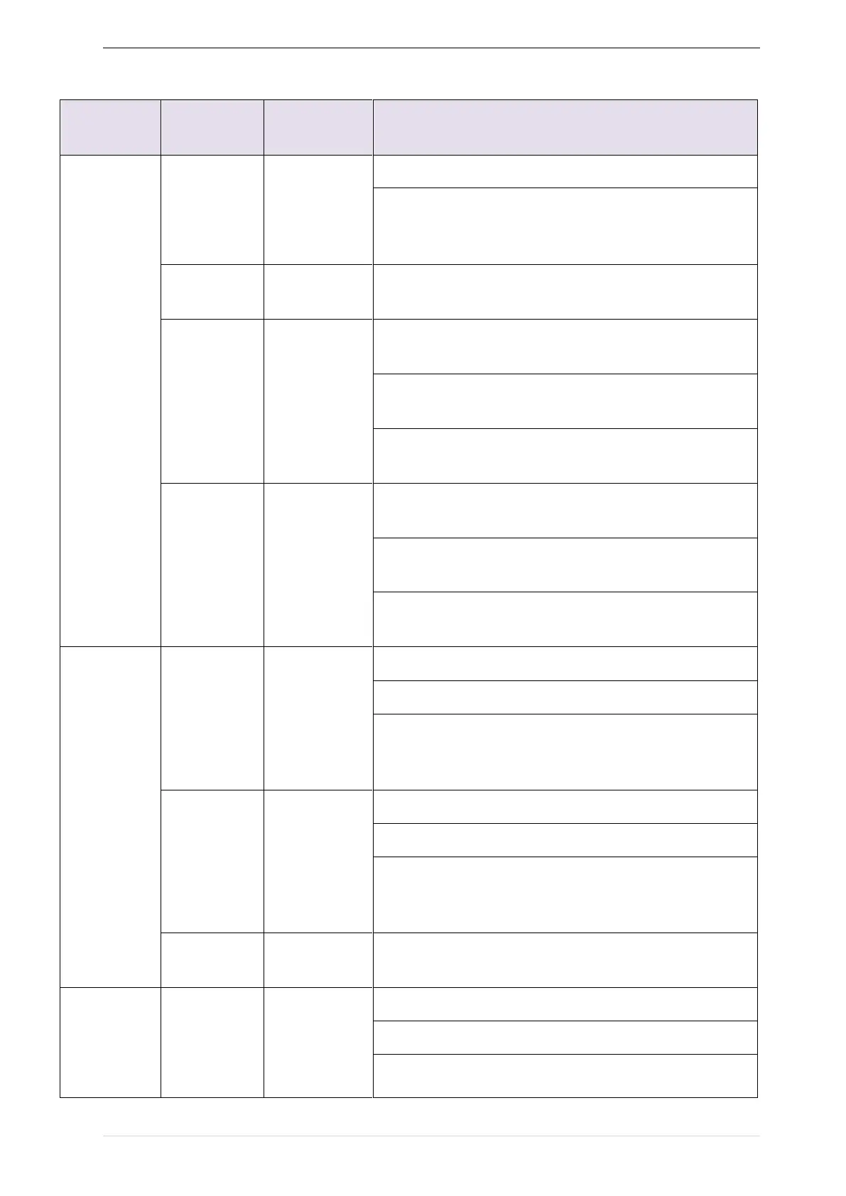
Table 3-20 IR610 control circuit terminal instruction
Terminal function description
Maximum output current:10mA,it provides power supply
to external potentiometer with resistance range of:
1KΩ~51KΩ
Internal isolation from COM
Input voltage:0~10V:Impedance 22KΩ,Maximum input
voltage
Input current:0~20mA:Impedance 500Ω,Maximum
input current
Through the jumper switch AI1 0 ~ 10V and 0 ~ 20mA
analog input switch, the factory default voltage input.
Input voltage:0~10V:Impedance 22KΩ,Maximum input
voltage
Input current:0~20mA:Impedance 500Ω,Maximum
input current
Through the jumper switch AI1 0 ~ 10V and 0 ~ 20mA
analog input switch, the factory default voltage input.
Output voltage:0~10V:Impedance ≥10KΩ
Output current:0~20mA:Impedance 200Ω~500Ω
Through the jumper switch AO1 0 ~ 10V and 0 ~ 20mA
analog output switching, the factory default voltage
output.
Output voltage:0~10V:Impedance ≥10KΩ
Output current:0~20mA:Impedance 200Ω~500Ω
Through the jumper switch AO1 0 ~ 10V and 0 ~ 20mA
analog output switching, the factory default voltage
output.
Internal isolation from COM
24V±10%,Internal isolation from GND
Maximum output current:200mA
To provide 24V power supply, generally used as a digital
input and output terminal power supply and external