Chapter3 product appearance and wiring IR610 high performance vector control frequency inverter user manual
- 14 -
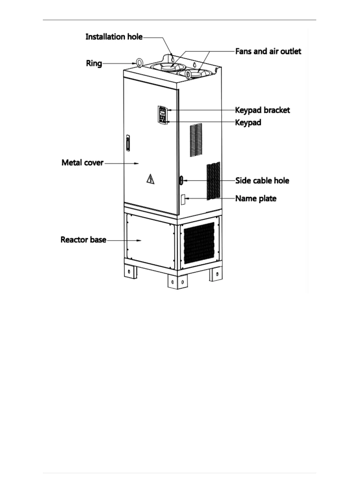
3-1-5 280KW-400KW
3.1.2Appearance and Mounting Hole Dimension
Keypay and keypad support size
The dimensions of the IR610 series keypad are shown in Figure 3-1. When installing the keypad on the outside of
the control cabinet, use the two screws on the back of the keypad to fix it (right side of Figure 3-1).