IR610 high performance vector control frequency inverter user manual Chapter3 Product appearance and wiring
- 19-
Appearance and installation dimension(mm)
Flooring mounting:H2*W*D=1560*550*450
Flooring mounting:H2*W*D=1495*730*450
Flooring mounting:H2*W*D=1575*785*450
Only for Flooring mounting:H2*W*D=1800x1080x500
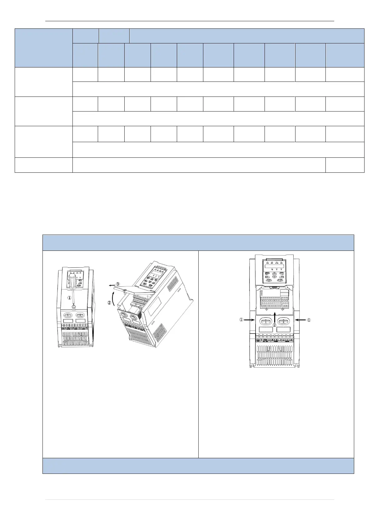
3.1.3Removal and installation of cover and inlet plate
SIZEA~SIZE C( 0.75KW-15KW) Removal and installation of cover and inlet plate:
Step 1: Open the top cover
① Unscrew the screw on the cover
② Lift up the cover
③ Remove the cover from the front
Step 2: Take out the inlet board
① Hold down the sides of the inlet plate with your
thumb and middle finger
② Press to disengage the buckle and pull it out of the
board