IR610 high performance vector control frequency inverter user manual Chapter 4 Operation and display
- 40 -
32 digits:
The left and right screen display, combined with the following figure to illustrate:
Dot1 is used to distinguish between the left and right screens. On indicates the left panel (upper 5 digits) and turns
off the right screen (lower 5 digits). When the left screen is displayed, Dot5 is used to indicate the sign digit. On
indicates that the value is negative, off indicates the value is Positive.
The display range of 32-bit unsigned numbers is 0 to 4294967295 (excluding decimal point), and the displayed
range of signed numbers is -2147483648 to 2147483647 (excluding the decimal point).
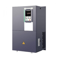
Binary data display
Binary number currently only supports 16 digits, points left and right screen display.
The leftmost digital tube is used to distinguish the left and right screens: the top digit segment lights up for the left
panel and the bottom segment segment lights for the right panel.
Remove the leftmost digital tube, from right to left, followed by Bit0 ~ Bit15. The upper segment is lit to indicate 1, the
lower segment to light to indicate 0.
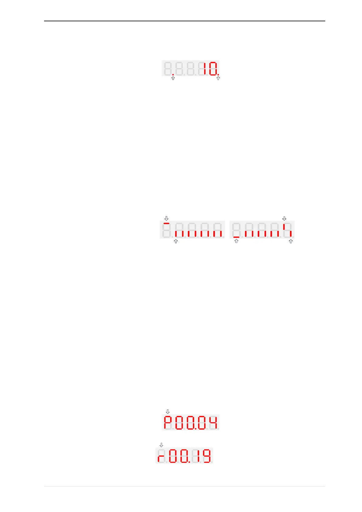
Parameter attribute identification
Editable parameters The leftmost LED displays "P"; the leftmost LED of the read-only parameter displays "r", as
shown below.