EasyManua.ls Logo

Vortex IR610 Series - Page 92

Vortex IR610 Series
179 pages
Print Icon
To Next Page IconTo Next Page
To Previous Page IconTo Previous Page
Loading...
IR610 high performance vector control frequency inverter user manual Chapter 5 function code table
- 88 -
12 Group Motor 1 VF control parameter
P12.00
VF curve
0:linear VF
1:Multi-point VF
2:VF to the 1.3
3:1.7 power
4:2.0 power
5:VF complete separation
6:VF Half separation
0
★
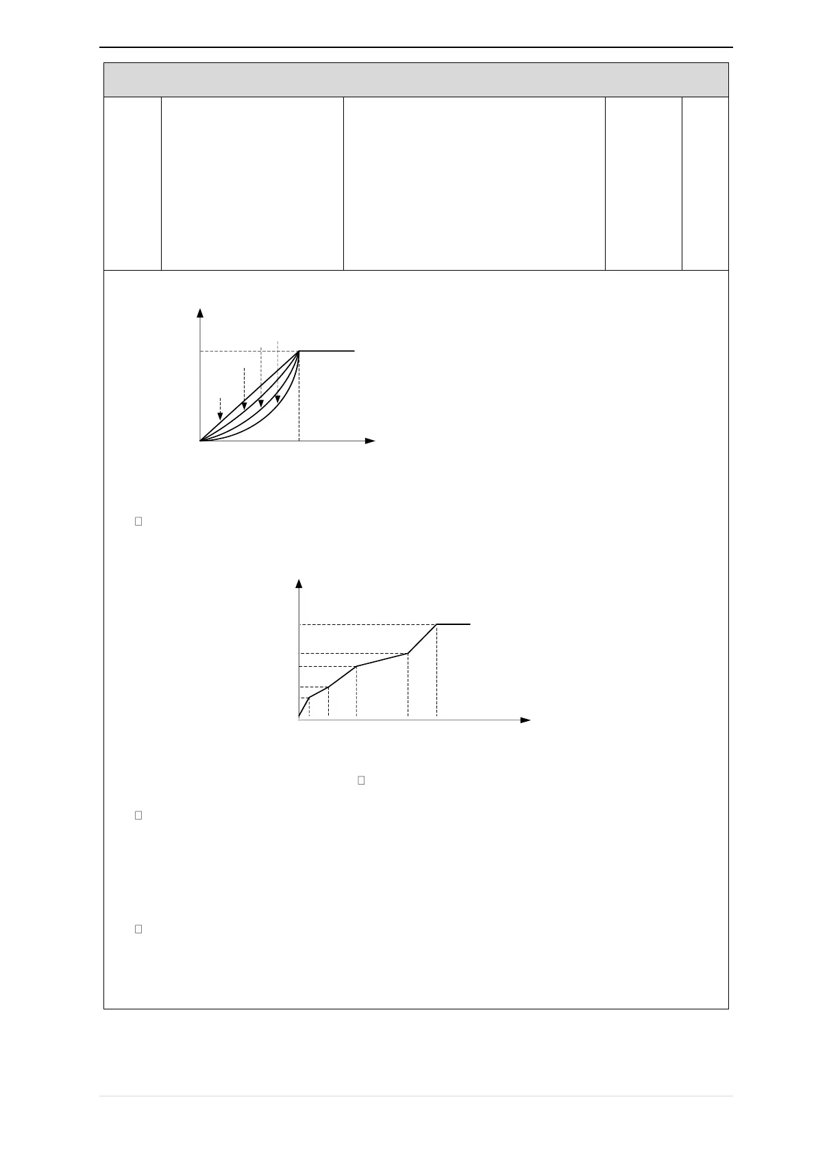
When the VF curve is straight line and power curve, the frequency-voltage curve is as follows:
Output
frequenc
y
Output
Voltage
Motor rated
frequency
0
Motor rated
Voltage
Straight line V/F
1.3
power
1.7powe
r
2.0
power
Figure 1:Straight line VF and 1.3、1.7、2.0 power VF
multi-stage line type VF curve:
Motor rated
voltage
Output
voltage
Motor rated
frequency
Output
frequen
cy
0
F
0
F
1
F
2
F
3
V0
V1
V2
V3
Figure 2: multi-stage line type VF curve
VF full separation
The output voltage and output frequency are completely independent. The output frequency is determined by the
frequency source. The output voltage is determined by P12.20. Suitable for applications such as variable
frequency power or torque motors.
VF semi-isolated
At this point the ratio of output voltage and output frequency given by the voltage source, the formula is as
follows::