15
ASSEMBLY OF PRODUCT
8 ASSEMBLY OF PRODUCT
8.1 Installation Diagram and Components
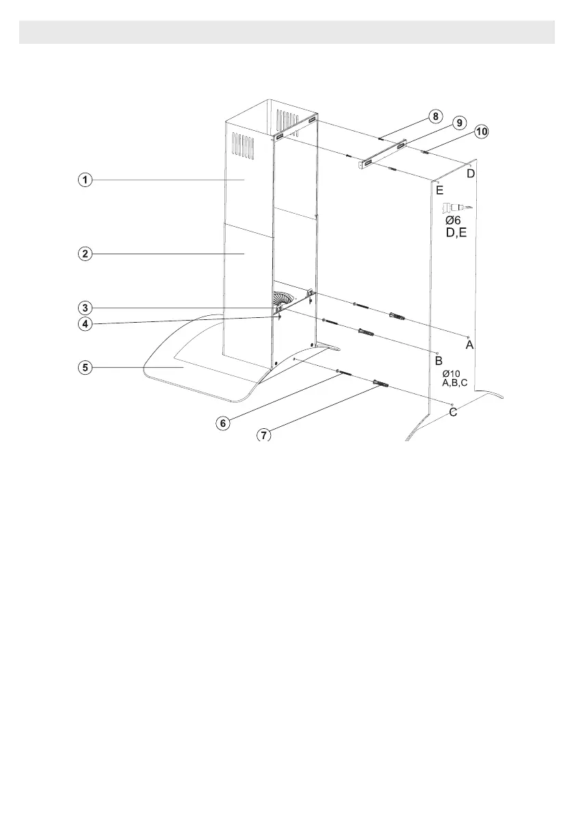
Fig. 10: ASSEMBLY INSTALLATION AND COMPONENTS
1. Inner Flue
2. Outer Flue
3. Product Hanging Plate
4. Product Hanging Plate Fixing Screw
5. Glass
6. 3x 5.5x60 Wall Mount Screw
7. 3x Ø10mm Plastic Dowel
8. 2x 3.9x22 Screw
9. Flue Connection Plate
10. 2x Ø6mm Plastic Dowel
■ Loosening the product hanging plate xing
screw (4) pull the hanging plates (3) upwards,
and x the hanging plated by re-tightening the
xing screw. Fig 10
■ Assemble the cooker hood with the help of
the assembly scheme. (Fig. 8 / 7)
■ Afx the assembly pattern on the wall, at the
specied height (See the minimum and maxi-
mum distances intended for the worktop, in the
assembly pattern). Perforate points A, B and
C.(Fig. 10)
■ Insert Ø10mm dowels (7) into the holes drilled
as A, B, C and D, and screw down the screws
at the points A + B so that 5mm space remains
between the screw head and the wall. (Fig. 10)
■ Hang it on the wall with the hanging plate of
the cooker hood.
■ Tighten A + B xing screws on the wall, and
completely secure the product at point C.