EasyManuals Logo

Wacker Neuson GV 7000A User Manual

Wacker Neuson GV 7000A
52 pages
To Next Page IconTo Next Page
To Previous Page IconTo Previous Page
Page #50 background imageLoading...
Page #50 background image
13 Diagram
50
100_0402_ew_0004.fm
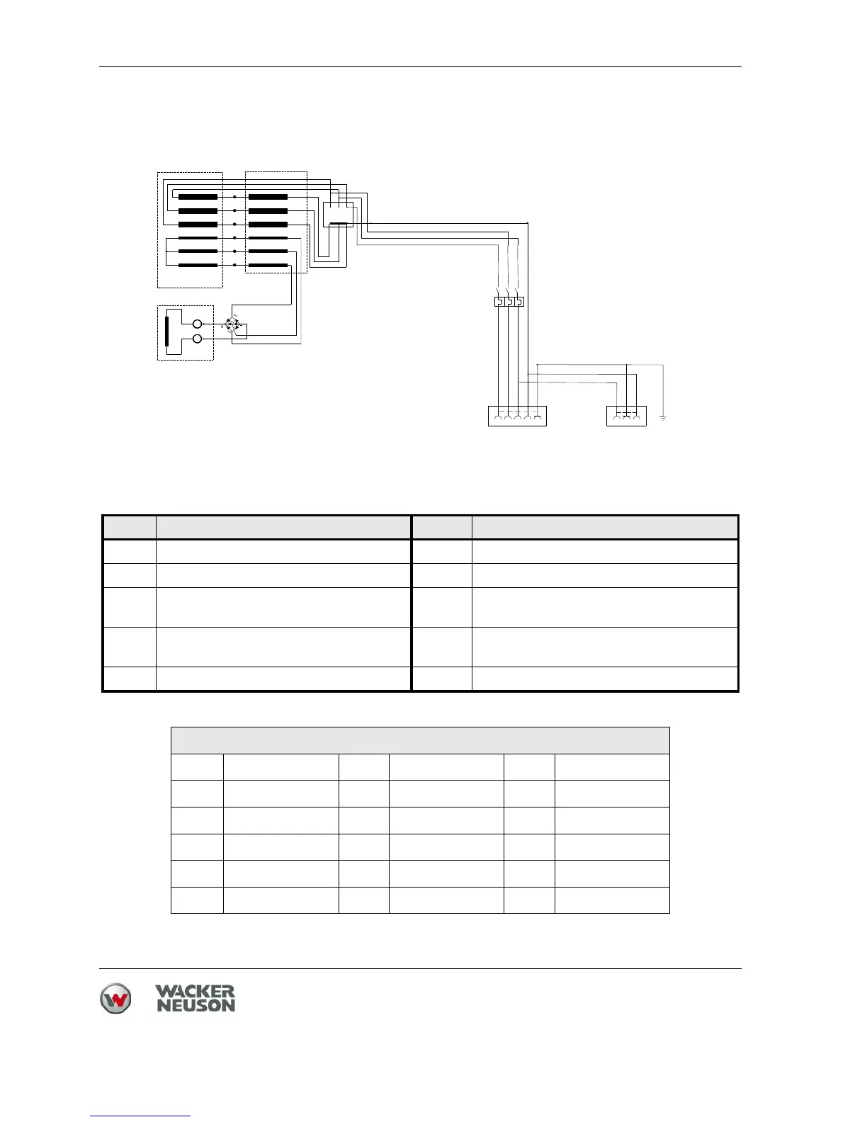
13.2 GV 7003A - Wiring diagram
Ref. Description Ref. Description
1 Main stator windings 6 Terminal board
2 Auxiliary winding 7 Circuit breaker
3 Voltage regulator (current rectifier) 8 Plug receptacle
230 V, 1Ø, 16A
4 Rotor windings 9 Plug receptacle
400 V, 3 Ø, 16 A
5 Compound (transformer) 10 Brushes
Color chart
B Black V Purple Or Orange
G Green W White Pr Purple
L Blue Y Yellow Sh Casing
P Pink Br Brown LL Light blue
R Red Cl Clear G/Y Green/Yellow
T Light brown Gr Gray
ROTOR
R
L
W
Br
B
B
W
W
Br
W
B
Br
Br
Br
L
5
W1
V1
U1
U2
V2
W2
Br
B
B
Br
W
1
B
W
Br
L
3~400V/16A
1~230V/16A
GND
L
GV 5003A
GV 7003A
6
7
8
9
3
4
10
wc_gr001249
Br
L
G/Y

Questions and Answers:

Question and Answer IconNeed help?

Do you have a question about the Wacker Neuson GV 7000A and is the answer not in the manual?

Wacker Neuson GV 7000A Specifications

General IconGeneral
BrandWacker Neuson
ModelGV 7000A
CategoryPortable Generator
LanguageEnglish

Related product manuals