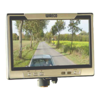
PerfectView M5L, M7L, M7LX Mounting the LCD monitor
31
7.3 Connecting the monitor electrically
The circuit diagram for the LCD monitor can be found in fig. d, page 7.
A
NOTICE!
Cables and connections that are not properly installed will cause malfunctions
or damage to components. Correct installation of cables and connections en-
sures lasting and trouble-free operation of the retrofitted components.
No. in
fig. d, page 7
Designation
1 Monitor
2 20-pin socket
3 Monitor line
4 20-pin plug
5 12–24 V positive cable (red): connected to the positive pole of the
ignition (connected positive, terminal 15) or the positive pole of the
battery (terminal 30).
6 Earth cable (black): connected to the negative pole of the voltage
source.
7 Cable (green): control input for video input C1,
e. g. for connection to the reversing light.
8 Cable (white): control input for video input C2,
e. g. side camera.
9 6 pin socket C1 (connection to video source 1)
10 6 pin socket C2 (connection to video source 2)
11 6 pin socket C3 (connection to video source 3)
M5L, M7L only: with video signal recognition)
12 M7LX only: 6 pin socket C4 (connection to video source 4,
with video signal recognition).
13 M7LX only: Cable (blue): Control input for video input C3.
_M5L_M7L_M7LX.book Seite 31 Montag, 7. Mai 2012 10:59 10
 Loading...