23
repairs at the unit
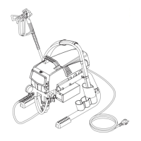
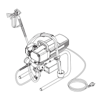
PS 3.25
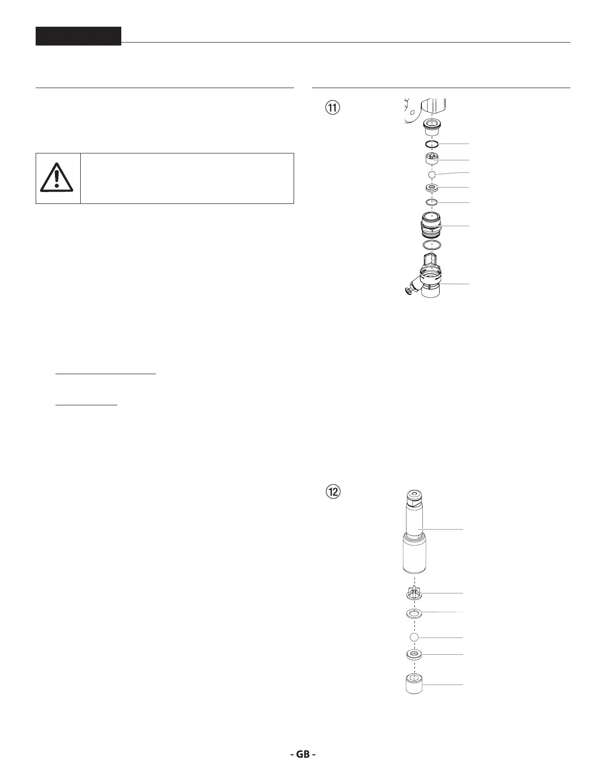
11.2 INLET AND OUTLET VALVE
1. Remove the four screws in the front cover and then remove
the front cover.
Danger of crushing - do not reach with the ngers
or tool between the moving parts.
2. The piston rod will need to be in the lower stroke position:
a. Turn the pressure control knob to minimum pressure. The
DESC screen should say “PRIME”.
b. Press the #1 key on the DESC control panel. The “CREEP
MODE” screen will now appear.
c. Slowly turn the pressure control knob clockwise to increase
the pressure. The crankshaft/slider assembly will begin to
move very slowly.
d. When it reaches the bottom, dead-center of its stroke, turn
the pressure control knob back to minimum pressure. The
crankshaft/slider assembly should stop.
3. Unplug the power plug from the outlet.
4. Unit on high-rider cart:
Screw o the suction tube.
Unit on stand:
Remove the retaining clip from the connecting bend at
the suction hose and pull o the suction hose.
5. Screw o the return hose.
6. Swivel the unit 90° to the rear in order to work more easily
on the material feed pump.
7. Remove the pusher stem clip and slide the pusher stem
housing (7) from the inlet valve housing (1).
8. Unscrew the inlet valve housing (Fig. 11, Item 1) from the
pump manifold.
9. Remove the lower seal (2), lower ball guide (3), inlet valve
ball (4), inlet valve seat (5) and O-ring (6).
10. Clean all the parts with the corresponding cleaning agent.
Check the inlet valve housing (1), inlet valve seat (5)
and inlet valve ball (4) for wear and replace the parts if
necessary. If the worn inlet valve seat (5) is unused on one
side, install it the other way round.
4
5
6
1
2
3
7
11. Unscrew outlet valve housing (Fig. 12, Item 8) from the
piston (9) with adjusting wrench.
12. Remove the upper ball cage (11), crush washer (10), outlet
valve ball (12), and outlet valve seat (13).
13. Clean all the parts with the corresponding cleaning agent.
Check outlet valve housing (8), outlet valve seat (13), outlet
valve ball (12), crush washer (10), and upper ball cage (11)
for wear and replace parts if necessary. If the worn outlet
valve seat (13) is unused on one side, install it the other
way round.
14. Carry out installation in the reverse order. Lubricate O-ring
(Fig. 11, Item 6) with machine grease and ensure proper
seating in the inlet valve housing (Fig. 11, Item 1).
11
10
12
13
9
8