WAGO-I/O-SYSTEM 750 Use in Hazardous Environments 41
750-492 2AI 4-20mA Differential Input
Manual
Version 1.1.0
Pos: 34.20 /Serie 750 ( WAGO-I/O-SYSTEM)/Einsa tz in Ex-Bereichen/Besonder e Bedingungen für den sic heren Ex-Betrieb gem. I EC-Ex-Zertifikat TUN 09.0001 X_ 2013_2 @ 15\mod_13686206 60911_21.docx @ 119786 @ 3 @ 1
7.2.3 Special Conditions for Safe Use (IEC-Ex Certificate TUN
09.0001 X)
1. For use as Gc- or Dc-apparatus (in zone 2 or 22) the Field bus Independent
I/O Modules WAGO-I/O-SYSTEM 750-*** shall be erected in an
enclosure that fulfils the requirements of the applicable standards (see the
marking) IEC 60079-0, IEC 60079-11, IEC 60079-15 and IEC 60079-31.
For use as group I electrical apparatus M2 the apparatus shall be erected in
an enclosure that ensures a sufficient protection according to IEC 60079-0
and IEC 60079-1 and the degree of protection IP64.
The compliance of these requirements and the correct installation into an
enclosure or a control cabinet of the devices shall be certified by an ExCB.
2. Measures have to be taken outside of the device that the rating voltage is not
being exceeded of more than 40 % because of transient disturbances.
3. DIP-switches, binary-switches and potentiometers, connected to the module
may only be actuated when explosive atmosphere can be excluded.
4. The connecting and disconnecting of the non-intrinsically safe circuits is
only permitted during installation, for maintenance or for repair purposes.
The temporal coincidence of explosion hazardous atmosphere and
installation, maintenance resp. repair purposes shall be excluded.
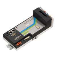
This is although and in particular valid for the interfaces “Memory-Card”,
“USB”, “Fieldbus connection”, “Configuration and programming interface”,
“antenna socket”, “D-Sub”, “DVI-port” and the “Ethernet interface”. These
interfaces are not energy limited or intrinsically safe circuits. An operating
of those circuits is in the behalf of the operator.
5. For the types 750-606, 750-625/000-001, 750-487/003-000, 750-484 and
750-633 the following shall be considered: The Interface circuits shall be
limited to overvoltage category I/II/III (non mains/mains circuits) as defined
in IEC 60664-1.
6. For replaceable fuses the following shall be considered: Do not remove or
replace the fuse when the apparatus is energized.
7. The following warnings shall be placed nearby the unit:
WARNING – DO NOT REMOVE OR REPLACE FUSE WHEN
ENERGIZED
WARNING – DO NOT SEPARATE WHEN ENERGIZED
WARNING – SEPARATE ONLY IN A NON-HAZARDOUS AREA
Pos: 34.21 /Dokumenta tion allgemein/Glie derungselemente/---Sei tenwechsel--- @ 3\mod_122110804507 8_0.docx @ 21810 @ @ 1
 Loading...
