WAGO-I/O-SYSTEM 750 Notes about this Documentation 5
750-492 2AI 4-20mA Differential Input
Manual
Version 1.1.0
Pos: 7 /Alle Serien (Al lgemeine Module)/Über schriften für alle Seri en/Hinweise zur Doku mentation/Hinweise zu di eser Dokumentation - Überschrif t 1 @ 4\mod_1237987661750_21.doc x @ 29029 @ 1 @ 1
1 Notes about this Documentation
Pos: 8 /Alle Serien (Al lgemeine Module)/Hin weise zur Dokumentation/ Hinweise/Hinwei s: Dokumentation aufbe wahren @ 4\mod_1237987 339812_21.docx @ 29026 @ @ 1
Always retain this documentation!
This documentation is part of the product. Therefore, retain the documentation
during the entire service life of the product. Pass on the documentation to any
subsequent user. In addition, ensure that any supplement to this documentation is
included, if necessary.
Pos: 9 /Alle Serien (Al lgemeine Module)/Über schriften für alle Seri en/Hinweise zur Dokume ntation/Gültigkei tsbereich - Übersc hrift 2 @ 12\mod_1338912448776_ 21.docx @ 96469 @ 2 @ 1
1.1 Validity of this Documentation
Pos: 10 /Serie 750 (W AGO-I/O-SYSTEM)/Hinweise zur Dokumenta tion/Gültigkeitsber eich/Gültigkeit sbereich Dokumenta tion Busklemme 750-xxxx, ohne Variantenangabe @ 14\ mod_1358944037947_2 1.docx @ 109346 @ @ 1
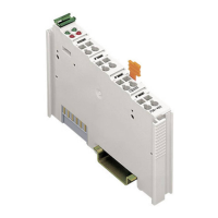
This documentation is only applicable to the I/O module 750-492
(2AI 4-20mA Differential Input).
Pos: 11 /Serie 750 (W AGO-I/O-SYSTEM)/Hinweise zur Dokumenta tion/Hinweise/Acht ung: Hinweis zur Dokume ntation Busklemmen 750- xxxx @ 4\mod_1237986979 656_21.docx @ 29023 @ @ 1
The I/O module 750-492 shall only be installed and operated according to the
instructions in this manual and in the manual for the used fieldbus
coupler/controller.
Consider power layout of the WAGO-I/O-SYSTEM 750!
In addition to these operating instructions, you will also need the manual for the
used fieldbus coupler/controller, which can be downloaded at www.wago.com.
There, you can obtain important information including information on electrical
isolation, system power and supply specifications.
Pos: 12.1 /Alle Serien (A llgemeine Module)/Hin weise zur Dokumentatio n/Urheberschut z ausführlich @ 4\mod_123 5565145234_21.doc x @ 27691 @ 2 @ 1
1.2 Copyright
This Manual, including all figures and illustrations, is copyright-protected. Any
further use of this Manual by third parties that violate pertinent copyright
provisions is prohibited. Reproduction, translation, electronic and phototechnical
filing/archiving (e.g., photocopying) as well as any amendments require the
written consent of WAGO Kontakttechnik GmbH & Co. KG, Minden, Germany.
Non-observance will involve the right to assert damage claims.
Pos: 12.2 /Dokumenta tion allgemein/Glied erungselemente/---Sei tenwechsel--- @ 3\mod_12211 08045078_0.docx @ 21810 @ @ 1

 Loading...


