Operating Instructions
33
STOPPING THE MACHINE
1. Pull the steering levers to the NEUTRAL-PARK
position and then move the FSC lever backward
to the NEUTRAL-PARK position.
2. Slow the engine to idle; put the throttle in the
IDLE position.
3. Disengage the blade clutch.
IMPORTANT: DO NOT disengage the blade
clutch with high engine speed (above 1/2 throt-
tle) since the brake action on the blade drive will
cause premature wear of the brake band.
WARNING
A brake stops the cutter blades from
freewheeling within ve (5) seconds after
disengaging the clutch. If the brake sys-
tem malfunctions and the blades do not
stop within ve (5) seconds, the brake
should be repaired or replaced before op-
erating the mower. Contact your Walker
dealer.
4. Turn the ignition switch OFF.
WARNING
Remove the key from the ignition switch
when leaving the mower unattended. This
will prevent children and inexperienced
operators from starting the engine.
5. Engage the parking brake. Also, engaging the
parking brake is recommended when stopping
or parking the machine in a confined space with
little tolerance for movement.
IMPORTANT: The hydrostatic transaxles lock
to prevent the mower from rolling freely with the
engine stopped. However, if the mower is
parked on a slope, it is necessary to ENGAGE
the parking BRAKE to prevent the mower from
creeping. This is due to a small amount of slip-
page in the transaxles, especially when
transmission fluid is warm.
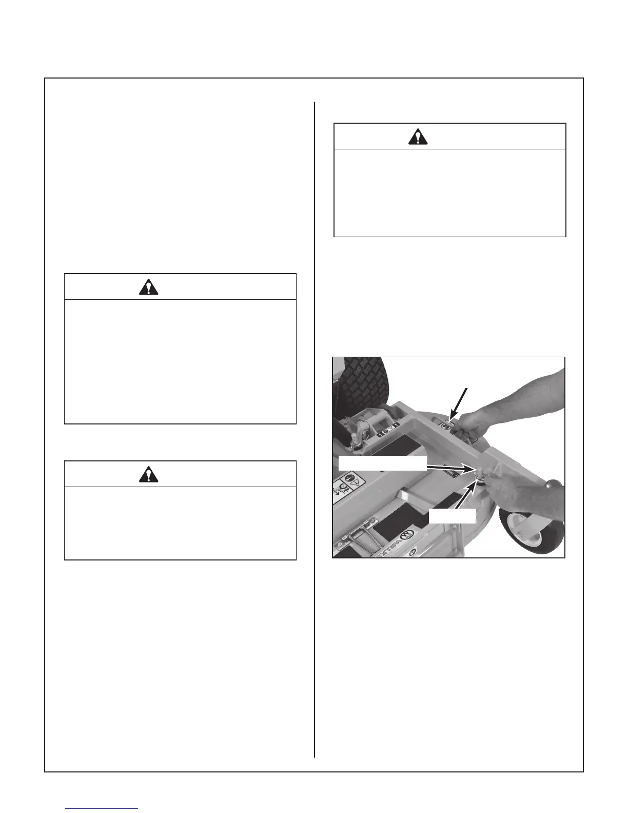
ADJUSTING CUTTING HEIGHT
WARNING
The engine must be stopped before ad-
justing cutting height. Disengage the blade
clutch (PTO), stop the engine, and remove
the ignition key. Wait for all move ment to
stop before getting off the seat.
Cutting height is adjusted by positioning the four (4)
re tainer hitch pins in a series of seven vertical holes
on the deck support pins. Lift handles have been
pro vided on each end of the deck to assist in raising
the deck while positioning the hitch pins. Cutting
heights range from 1 in. (25 mm) [top holes] to 4 in.
(102 mm) [bottom holes] in 1/2 in. (13 mm) incre-
ments.
Lift Handle
Deck Support Pin
Hitch Pin
Cutting Height Adjustment