Assembly Instructions
22
Align
Arrows
Coupler
Installation Tool
Tractor
PTO Shaft
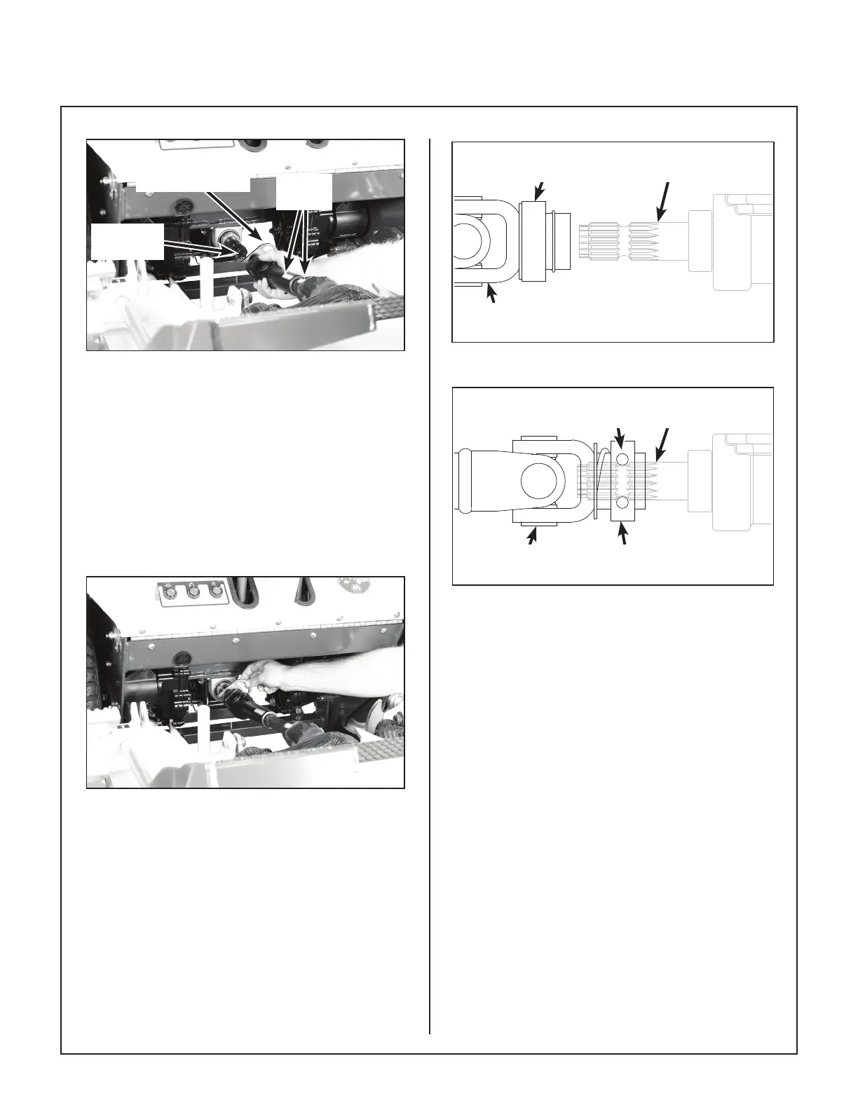
PTO Shaft Connection
(Shown with Debris Guard Removed for Clarity)
5. Reaching under the tractor, slide the PTO cou
pler tube onto the deck drive shaft (align arrow
decals), then install the coupler quick discon
nect onto the tractor PTO drive shaft. Refer to
the PTO Shaft Connection photo.
6. Remove Coupler Installation Tool from the quick
disconnect ring and make sure the ring has
“snapped” securely on the spline shaft.
Coupler Installation Tool Removal
(Shown with Debris Guard Removed for Clarity)
IMPORTANT: DO NOT operate tractor with
Coupler Installation Tool installed.
IMPORTANT: To prevent damage to the mow
er, make sure the PTO quick disconnect is se
curely locked on the tractor, with the locking
balls fully seated in the groove and the ring in the
locked position (refer to the Quick Disconnect
Ring “Locked” Position illustration). After in
stallation, pull on the PTO coupler to check for
security.
Coupler Ring in
Released Position
PTO Drive
Shaft
PTO Coupler
UJoint
Quick Disconnect Ring “Released” Position
Coupler Ring in
Locked Position
PTO Drive
Shaft
PTO Coupler
UJoint
Internal Balls
Locked on Shaft
Quick Disconnect Ring “Locked” Position
7. Raise the mower body (instead of lifting the
front of deck) and clip the counterweight springs
to the receptacle on front of body. Lower the
body to tension the springs. (Refer to Deck
Counterweight Spring Installation photo.)
8. With the counterweight springs connected, the
weight on the deck caster wheels should be
190 to 230 Ib (86 to 104 kg); this adjustment is
preset at the factory.