Assembly Instructions
23
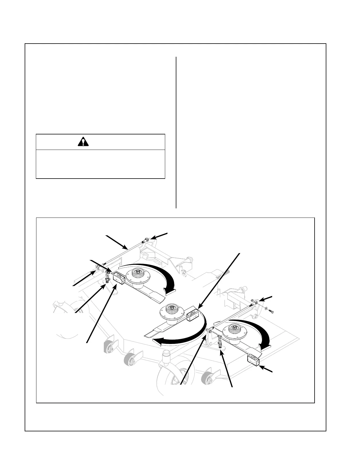
Deck Leveling
1. Position mower on a smooth, level surface. Set
the cutting height to the highest position - 5 in.
(127 mm) - for easy access under the deck to
measure blade height. Refer to ADJUSTING
CUTTING HEIGHT in Operating Instructions.
NOTE: A block of wood cut 5 in. (127 mm) high
is a convenient gauge to measure blade height
above ground during the leveling process.
WARNING
The machine must be shut off during this
procedure.
2. Check the side-to-side level. Rotate the out side
blades sideways and measure the distance
from blade tip to ground on each side. If
measurements vary more than 1/8 in. (3 mm),
adjust the height adjustment rod on the high side
to level the deck.
3. Check the front-to-rear level. Rotate the cen ter
blade to point forward. Measure the distance
from blade tip to ground on the front and rear. The
rear of the blade should be 1/16 to 1/8 in.
(2 to 3 mm) higher than the front of the blade;
remove the chain from the deck height adjuster
clevis and adjust equally to achieve at least 1/16 in.
(2 mm) difference. Reinstall chains.
NOTE: The mower deck and support frame are
jig welded; within normal tolerances, very little,
if any, adjustments should be required to level
the deck. Tire pressure will inuence the level-
ness of the deck. Check the tire pressure as a
possi ble cause of the deck not being level.
Height Adjustment
Rod
Rear
Rod End
5 in. (127 mm)
Wood Block
Should be 1/16 in. (2 mm)
to 1/8 in. (3 mm) Higher
at the Rear of the Blade
Rear
Rod End
Front
Rod End
5 in. (127 mm)
Wood Block
Use Front Clevis to Raise or Lower
for Front-to-Rear Level
Front
Rod End
Should Not Vary More
Than 1/8 in. (3 mm)
Side-to-Side
Use Front Clevis to
Raise or Lower for
Front-to-Rear Level
Deck Leveling