Assembly Instructions for the R21
63
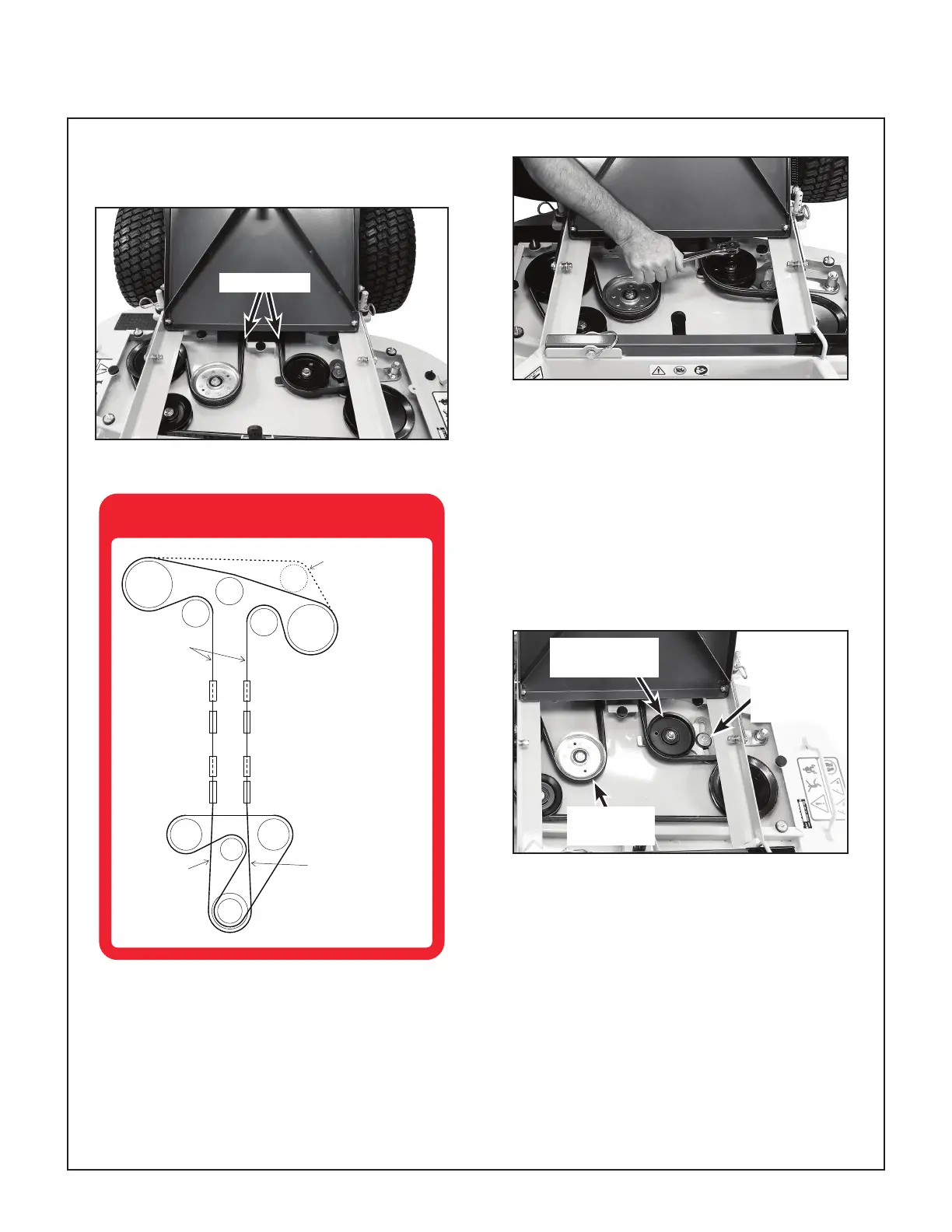
guide. Be sure there is 1/4 twist on each side
as the belt leaves the deck cover area.
1/4 Twist
Quarter Twist on Each Side
BELT ROUTING
1600-1
GROUND DRIVE BELT
WALKER P/N 1250
BLADE DRIVE BELT
42": WALKER P/N 1731-1
48": WALKER P/N 1731
1/4 TWIST
1/4 TWIST
1/4 TWIST
42" DECK
Belt Routing Decal
15. Using a 9/16 in. (14 mm) socket wrench (with
a long drive handle for increased leverage),
rotate the deck idler arm clockwise and install
the belt on the LH spindle pulley. Release the
idler arm to tension the belt.
Tension Belt with Deck Idler Arm
16. With the drive belt in place, check the position
of the stop in the slot of the belt tensioning
idler arm—the stop should be near the middle
of the slot. If the stop is on one side or the
other (due to belt length variation), the xed
rear idler pulley on the RH side of the deck
has three (3) adjustable mounting positions.
Adjust the xed idler pulley mounting position
to put the tensioning arm stop in the middle of
the slot.
Stop in the
middle of
tensioning
slot
Fixed Rear
Idler
Belt Tensioning
Idler
Check Position of Stop in the Slot
17. Reinstall the belt cover on the deck.
NOTE: The side with the longer angled por-
tion is the LH side.
18. Lower the footrest.