17 | P a g e
Wallgate Thrii®
PRODUCT MANUAL Issue 5_3
ORIGINAL INSTRUCTIONS
© 2013 Wallgate Ltd.
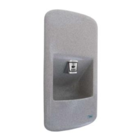
Fig.10 Hinge adjustment. 10a showing depth adjustment. 10b showing side adjustment
Note hinge release spigot in place
5. Once the fit has been checked, close the fascia fully to check the locking bar operation. The
locking bar is spring-loaded and may require a firm push to engage correctly. To re-open insert
the key provided into the fascia lock release at the base of the fascia, ¼ turn anti-clockwise and
push the key up to disengage the lock and allow the fascia to open freely see Fig. 2.
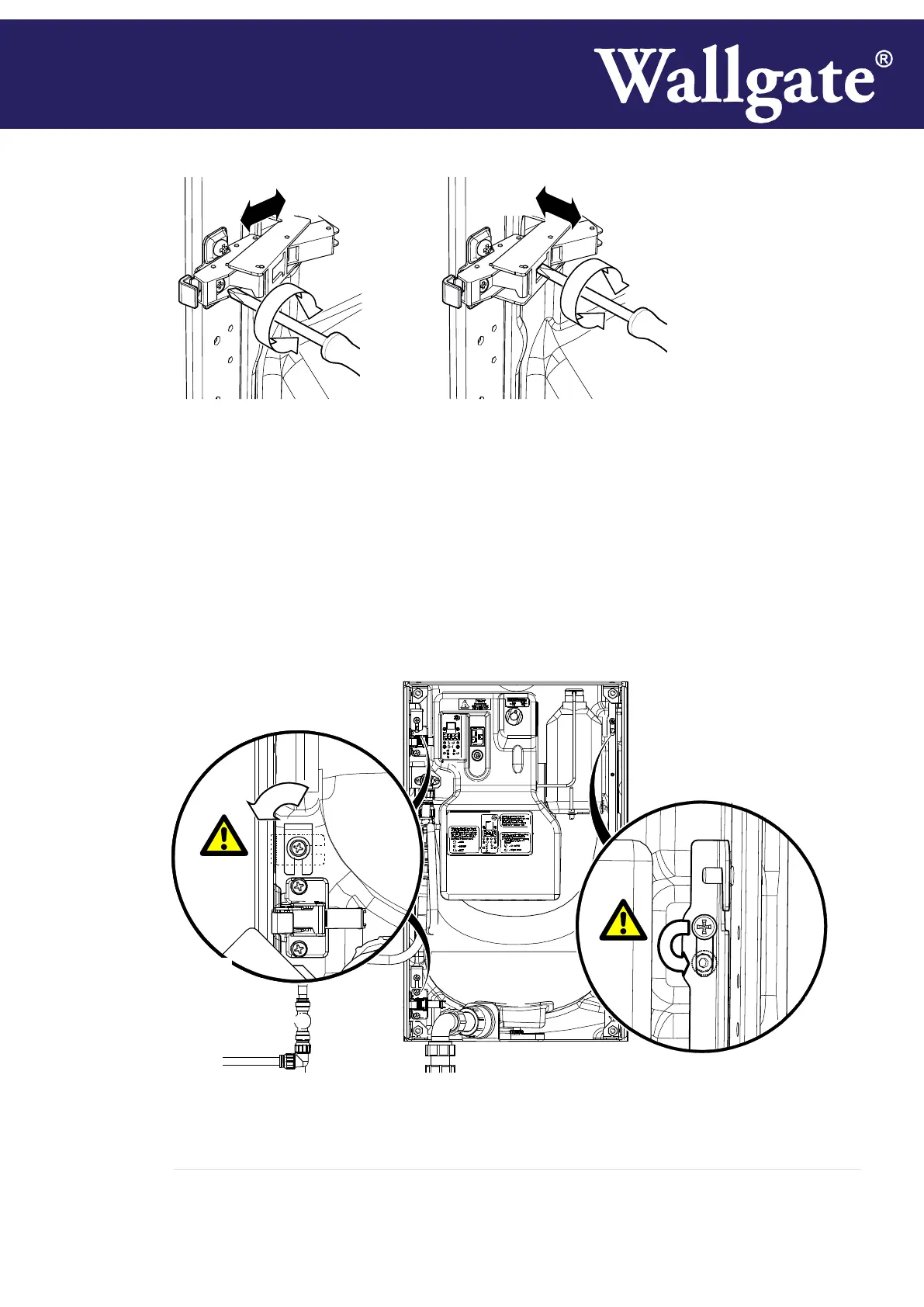
6. For installations where front access is not required in addition to the hinge release lock, engage
the 2 hinge side locks, rotating into the slot provided in the frame as shown in
Fig. 11a, and when the lock bar has been fully engaged, relocate the top screw fixing into the
locking position below, as shown inFig. 11b
Fig.11 Securing the unit for rear-access only, 11a showing hinge side locks, 11b showing fixing
repositioning