EasyManua.ls Logo

Wallgate WDC200 - Attach the Controller Unit

Wallgate WDC200
33 pages
Print Icon
To Next Page IconTo Next Page
To Previous Page IconTo Previous Page
Loading...
10
Product Manual WDC200 Electronic Control
Revision 18
5.3 Attach the Controller Unit
To attach the control unit to the wall, do the following:
Mark the attachment points for the control unit on the wall. Make sure the cables
from the solenoid valves and Piezo touch buttons are of sufficient length to reach
the control unit. Refer to figure 1 for the location of the mounting feet.
Drill four mounting holes using a suitable drill bit.
Use suitable wall plugs if necessary.
Attach the unit to the wall using four round head screws.
NOTE: When mounting the unit, make sure the cable sockets at the bottom of
the unit point downwards.
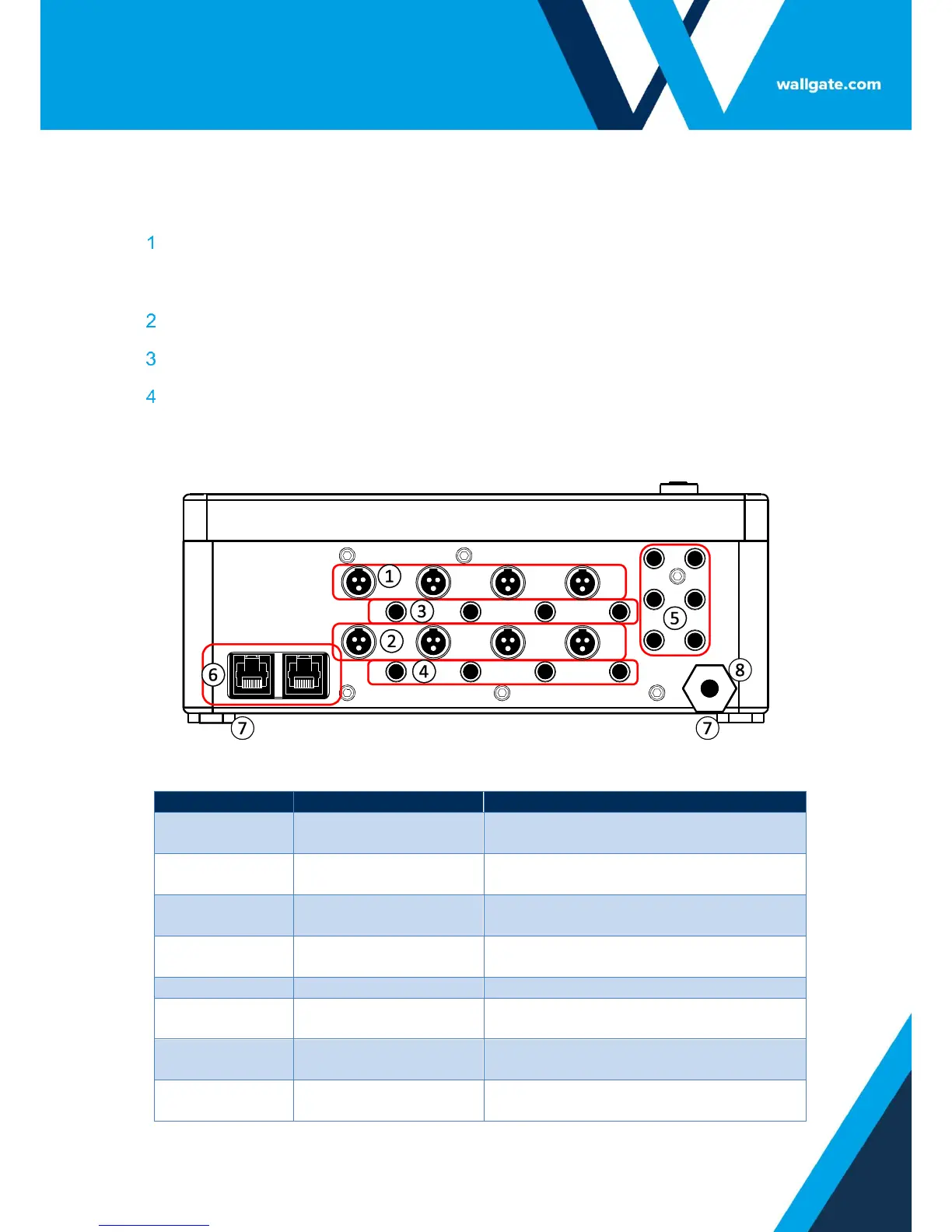
Figure 1.WDC200 Lower Panel
Table 2. Legend for Figure 1
Description
Function
Water Valve Cable
Sockets Room 1
Output to washbasin, WC and shower
valves in Room 1
Water Valve Cable
Sockets Room 2
Output to washbasin, WC and shower
valves in Room 2
Input Device Sockets
Room 1
Input from Piezo touch button or
infrared sensors Room 1
Input Device sockets
Room 2
Input from Piezo touch button or
infrared sensors Room 2
Auxiliary Inputs
Inputs for optional remote controls
Network Link Sockets
Input and output sockets for Ethernet
connection
Mounting feet
Use the feet to mount the control unit
to the wall
Power cable
Electrical power supply cable 1 metre
in length

Related product manuals