Product Manual WDC200 Electronic Control
Input from WC Flush
Piezo touch button /
sensor
User input (Piezo touch button or
IR sensor) for WC Flush Room 2
Input from Shower Piezo
touch button / sensor
User input (Piezo touch button or
IR sensor) for Shower Room 2
Input from Basin Cold
Piezo touch button /
sensor
User input (Piezo touch button or
IR sensor) for Basin Cold Room 2
Input from Basin Hot
Piezo touch button /
sensor
User input (Piezo touch button or
IR sensor) for Basin Hot Room 2
Remote Lockout 1
(default)
Remote Lockout 2
(default)
WC Remote Flush
1(default)
WC Remote Flush 2
(default)
WC Half Flush 2 (default)
Optional Inputs, I, J, K, L, M, and N are used when it is necessary to:
• Lockout or disable the basin shower and WC from a remote switch.
• Remotely flush the WC pans.
• Provide the half flush option.
• Clear room lockouts
• Purge all outlets
• Connect a hygiene purge water flow sensor.
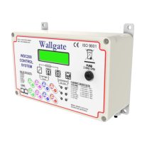
There are four types of sockets in the control unit:
• Eight 3 pin female sockets, to connect the unit to the solenoid valves. These
sockets are used to connect the water valve solenoids, 2 sockets for the WC
flush valves, 4 for the wash basin control valves and 2 for the shower control
valves.
• Eight 3.5 mm female sockets, to connect the unit to the Piezo touch buttons.
• Six 3.5 mm female sockets, to connect the unit to optional remote controls.
• Two RJ45 connectors are provided to connect the control unit to an Ethernet
network.
The socket assignments are given on the front of the unit. Refer to the label on the
front of the unit. Also see Figure 2 on page 11 and
Table 3 for the socket assignment.