Operating Manual WLVCM-BA-10
EN
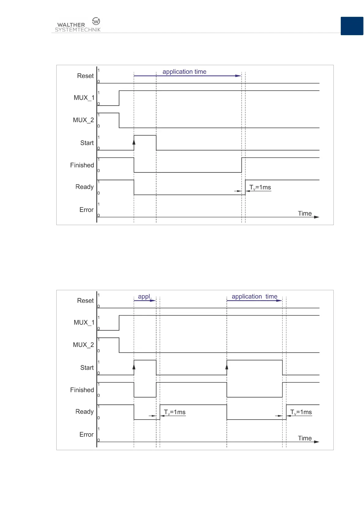
If the single-pulse-triggered application time is larger than the duration of the applied HIGH signal level
at the “Start“ digital signal inlet (see also figure 18), the digital outlet signal “Ready“ will also be switched
back to HIGH directly after the end of the application process. The time delay here is 1ms.
Figure 19 – Signal curve for performing an application cycle which is triggered by a single pulse; digital inlet signal
„Start“ is applied shorter than the application time
Figure 19 shows you an example for a signal curve of an application process which is triggered by a
permanent signal. In this case, the application time depends upon the time during which the digital inlet
signal “Start” shows a HIGH signal level. As shown in figure 19, this can be used for realizing different
application times. In the case of an application process which is triggered by a permanent signal, the
digital outlet signal “Finished” will follow directly after the digital inlet signal with inverted signal level.
Figure 20 – Signal curve for the performance of an application cycle which is triggered by a permanent signal